Characterization of artesian flow and heat transition in an ATES research wellbore using DTS monitoring and numerical modelling
Liang Pei
Lioba Virchow
Guido Blöcher
Stefan Kranz
Ali Saadat
In the practice of Aquifer Thermal Energy Storage (ATES), the hydraulic connection to the wellbore of any other aquifers besides the planned thermal storage should be identified and prohibited in order to operate the ATES system in a sustainable way. The present study was aimed at locating an artesian aquifer other than the planned thermal storage in an ATES research wellbore (Berlin, Germany). Therefore, we analysed the wellbore temperature as monitored with a single fiber optic cable using the Distributed Temperature Sensing (DTS) technique in a series of artesian flow tests. The change in the wellbore temperature, the depth-dependent thermal gradients and the isotherms as derived from the DTS-monitored data helped positioning the artesian aquifer in the depth interval from 220 to 230 m. In addition, the transition from cooling to heating in the wellbore sections above the depth of 40 m was applied calculating the velocity of the artesian flow. A numerical model accounting for such artesian flow was built via matching the simulated volumetric flow rate to the wellhead measurements. The consistency of the simulated wellbore temperature with the DTS measurements validated this numerical model as well as the positioning of the artesian aquifer. These simulates extensively visualized the effect of the artesian flow on the near-wellbore temperature field.
- Article
(7788 KB) - Full-text XML
- BibTeX
- EndNote
Surplus heat as stored in an ATES (Aquifer Thermal Energy Storage) system in summer could partly meet the increasing regional demand of energy in winter. The hydraulic connection of an artesian aquifer other than the planned aquifer thermal storage to the wellbore would hinder the sustainable operation of the ATES system. The cross flow from such artesian aquifer to the storage via the wellbore could lower the temperature of the injected water during the shut-in stage and drive the stored heat to farther radial extension from the wellbore centre (Blöcher et al., 2024). The contribution of this artesian aquifer to the production could further lower down the temperature of the produced water. Therefore, it is necessary to identify the existence of such artesian aquifer and prohibit its hydraulic connection to the wellbore-storage system. The existence of an artesian aquifer may not be determined during the drilling of a wellbore due to the high density of the applied drilling fluid as well as to the mud cake as formed on the wall rock. Instead, such aquifer might be exposed when the mud cake is removed shortly before the cement job. Under this circumstance, it would not be practically feasible to implement additional well logging in order to position the artesian aquifer, leaving the wall rock unsupported under the potential risk of breakout or collapse. The conventional electronic sensors could be deployed ahead of the removal of the mud cake. However, it would not be easy to apply this discrete deployment in an economical way when the position and the thickness of the artesian aquifer are not known. In comparison, the distributed sensing techniques using fiber optic cables appear to be more robust and cost-friendly.
Beside the Distributed Acoustic Sensing (DAS; Liu et al., 2024, Shetty et al., 2024) and the Distributed Strain Sensing (DSS; Doonechaly et al., 2024), which are specialized in monitoring vibration and deformation respectively, the Distributed Temperature Sensing (DTS; Lipus et al., 2021) could be multi-functional. The DTS fiber optic cable as deployed e.g., to the outer lateral surface of the filter casing, could monitor the temperature-depth profiles within a studied time span. The changes in such monitored temperature at studied depths and time instants could reflect the movement of e.g., the artesian fluid as a heat carrying medium. These monitored changes in temperature assist in positioning the artesian aquifer.
In the present study, we conducted a series of artesian flow tests by producing artesian fluid from the ATES research wellbore Gt BTrKoe 1/2021 (Berlin, Germany) so as to induce changes in the wellbore temperature and to locate the artesian aquifer. The DTS-monitored temperature profiles throughout these tests were analysed, and manifested: (1) the process of fluid- and heat transport related to the artesian flow, (2) the depth interval of low thermal gradients and (3) the depth interval in which the artesian aquifer situated. In an effort to verify the outcome of the data analyses, we modelled the artesian flow in the wellbore-aquifer system and validated the model by comparing the simulated temperature in the wellbore to the DTS measurements. Moreover, the applicability of the DTS-monitored temperature data in characterizing the artesian flow was discussed. The DTS technique appeared to be helpful revealing the fluid flow in the wellbore within the practice of ATES.
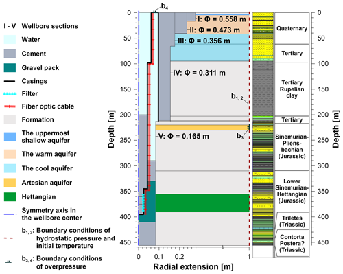
The research wellbore Gt BTrKoe 1/2021 is located in Berlin, Germany, and has been employed for evaluating the feasibility of adopting the Hettangian formation (Fig. 1) as an ATES to partly meet the regional and seasonal energy demand. The logging and the analyses on the drill cuts and the drill cores (Piekarski et al., 2022) revealed the presence of the Quaternary to Triassic sedimentary rocks at the site of this research wellbore. The uppermost Quaternary sediments down to the depth of 62 m consisted of sandy to gravelly moraine- and river valley deposits. The underlying Tertiary formation down to the depth of 217 m consisted of Miocene lignite and mica-rick quartz sands as well as Oligocene Rupelian clay. The Rupelian clay represents the main aquitard separating the overlying freshwater aquifers from the potential ATES aquifers. The lithology of the underlying Jurassic Pliensbachian formation as well as of the Sinemurian to Hettangian formation was featured by mudstones, siltstones, intercalated mud/silt/sand, marlstones, conglomerates and sandstones. The lowermost Triassic formation consisted of marlstones, calcareous sandstone and siltstone, mudstone and decimetre-sized coal seams (Fig. 1). An uppermost shallow aquifer at a temperature of 8 °C was located above the depth of 5 m. An aquifer of warmer water up to 14 °C as well as an aquifer of cooler water down to 11.6 °C situated in the depth intervals from 5 to 40 m and from 40 to 100 m, respectively (Fig. 1). The artesian aquifer was positioned between 220 to 230 m (see Sect. 4.1).
The wellbore Gt BTrKoe 1/2021 was completed to the depth of 456 m. The diameters of the wellbore sections I to V ranged from 0.558 to 0.165 m. The anchor casing of an inner diameter of 0.194 m was deployed down to 211.5 m. The filter casing was deployed down to 395 m. The inner diameters of the filter casing amounted to 0.05 m below 345 m, to 0.089 m in the depth interval from 98 to 345 m and amounted to 0.121 m above 98 m. The annular space between the anchor casing and the wall rock at the wellbore sections I to IV was cemented. During the cement job in the annulus between the both casings, the cement slurry entered the filter casing through the gravel pack as well as the filter, and finally reached the depth of 200 m due to the reduced functioning of the cement packer at 290 m. The DTS fiber optic cable was deployed on the outer lateral surface of the filter casing down to 394.8 m.
3.1 Test procedure
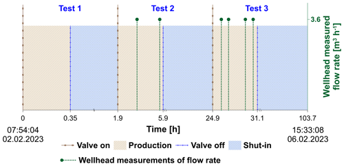
The artesian flow tests were conducted in order to monitor the changes in temperature in the near-wellbore subsurface as induced by the artesian flow and to locate the depth interval of this aquifer. These tests were subdivided into the production- and shut-in stages (Fig. 2). In the production stages, a wellhead valve was opened so that the annulus between the production casing and the anchor casing was connected to the atmosphere yielding artesian outflow. Therein, the wellhead flow rate was determined using a measuring bucket of a volume of 5 L as well as a stop watch. During this stage, fluid samples were also taken and analysed in parallel studies for microbial diversity and hydrochemical compositions (Norden et al., 2023). In the shut-in stages, the wellhead valve was closed so that the artesian outflow was ceased. During the tests, the wellbore temperature was monitored using the DTS fiber optic cable at a spatial resolution of 0.5 m and at time intervals of about 105 s.
3.2 Setup of numerical model
We implemented numerical modelling in the effort to validate the positioning of the artesian aquifer using the DTS-monitored temperature data. The modelled artesian flow and the concomitant heat transition in the near-wellbore subsurface helped understanding the hydrothermal processes during the conducted artesian flow tests. The present studied wellbore-aquifer system was built in a 2D-axisymmetric model being confined in a radial extension of 1m from the wellbore centre as well as between the ground surface (0 m) and the depth of 456 m (Fig. 1). Therein, the axis of symmetry was set at the left vertical model edge representing the centre of the wellbore. The Darcy's law and the Navier-Stokes equations were coupled simulating the fluid flow in the porous media and in the wellbore, respectively. Thereby, the transition of the flow regimes from porous flow to free flow was accounted for in the modelling. The heat transition in the wellbore-aquifer system was modelled considering both of the thermal conduction and thermal convection. A steady state study was firstly implemented, so as to evaluate the initial values of pressure and temperature in the modelled domain, respectively. Therefore, a hydrostatic pressure boundary (b1) accounting for the gravity of groundwater and a temperature-depth profile (b2) as monitored prior to the present tests were defined at the right model edge, respectively. These two boundary conditions b1, 2 were sustained in the subsequent transient studies modelling the production- and the shut-in test stages, respectively. In a transient study following the steady state simulation, we modelled the artesian flow from the Jurassic sand (see Sect. 4.1) into the wellbore during production. Therefore, we defined an apparent overpressure of 26.25 kPa in addition to the hydrostatic pressure between 220 to 230 m on the right model edge (Fig. 1, b3), and assigned a measured overpressure of 22 kPa to the top model edge of the annulus between the both casings (Fig. 1, b4), respectively. In the subsequent transient study modelling a shut-in stage, the top edge of the annulus (b4) was set into a non-flux boundary instead.
The equilibrium in hydrostatic pressure and in temperature within the modelled domain as attained in the steady state study provided a basis, on which the changes in pressure and temperature as induced by the artesian flow could be computed. The differential pressure between the two boundaries b3, 4 as applied in the transient study modelling the production stage mimicked such a hydraulic state that the wellhead situated beneath a potentiometric surface. The pressure gradient between these two boundaries gave rise to an artesian flow. By setting the top model edge b4 into a non-flux boundary for modelling the shut-in, the pressure in the annulus between the both casings could achieve equilibrium to the value as defined at the boundary b3. Thereby, the artesian flow could cease. The heat transition as induced by the artesian flow was modelled by coupling the simulated fluid flow to the temperature as defined at the Jurassic sand strata (220 to 230 m, b2). The heat flux into the wellbore-aquifer system was determined by the differential temperature of the fluid flow to the apparent values in the modelled domain and the simulated flow velocity, as well as the density and the specific heat of the fluid. The computed temperature in the modelled domain and the boundary b2 as sustained in the transient studies yielded a thermal gradient toward the right model edge. This thermal gradient permitted simulating the conductive heat transition from the wellbore into the farther subsurface.
4.1 Measurements
The initial subsurface temperature down to the depth of 394.8 m ranged from 8 to 22 °C. The temperature-depth profile above 100 m was featured by a reversed thermal gradient between 10 and 50 m. This reversed gradient was confined by the temperatures of 11.6 and 14 °C at the depths of 48.5 and 16 m, respectively (Fig. 3a). By the end of the subsequent production stages, the wellbore was heated up showing the maximum increase in temperature of 4.5 °C at the depth of 100 m (Fig. 3b, c). At the end of shut-in, the temperature profiling approached the initial state presenting a differential temperature of up to ±1 °C. It is noticeable that by the end of the first production (Fig. 3a) the wellbore section above 40 m was cooled down showing a maximum decrease in temperature of 1.8 °C at the depth of 10 m. Concomitantly, the wellbore section between 50 and 210 m was slightly heated up showing a maximum increase in temperature of 1.5 °C only, in contrast to the cases in the subsequent production stages. In addition, substantial increase in temperature was only observed above the depth of 220 m throughout the present tests. The apparent thermal gradients in different wellbore sections at the studied time instants (Fig. 3) are presented in Table 1. In the upper wellbore (100 to 220 m), the production yielded the thermal gradients of lower magnitudes as compared to the values by the onset and by the end of each test. The thermal gradients below 220 m did not show substantial changes during the present tests, however, the values in the depth interval from 220 to 240 m were apparently lower than the counterparts below 240 m.
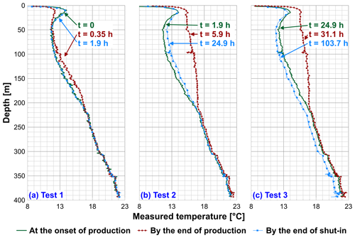
Figure 3Temperature-depth profiles as measured using DTS fiber optic cable at studied time instants during the present artesian flow tests.
Table 1Gradients in measured temperature in different wellbore sections at studied time instants.
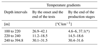
* The apparent high value is due to the short production stage in the first test and the so induced mild increase in the wellbore temperature.
Moreover, the temperature in different wellbore sections varied at the rates ranging from −10 to 10 °C h−1 in the production stages, and changed at the rates from −2 to 2 °C h−1 in the shut-in stages (Fig. 4). Here, the positive values denote heating and the negative values indicate cooling. In comparison to the steady state temperature profiling (Fig. 4a), the uppermost wellbore section at the aquifer down to 5 m was heated up within 0.1 h after the onset of respective production stage (Fig. 4b–d). Concurrently, the warm wellbore section at the aquifer down to 40 m underwent cooling, and the wellbore sections between 40 and 220 m was heated up. As the production stages proceeded, the temperature in the uppermost wellbore section started to decrease for about 0.15 h, before this section was again heated up. Concomitantly, the warm wellbore section underwent extensive cooling for approximately another 0.1 h, before heating started. In the sections below 40 m the heating process continued throughout the productions. From the onsets of shut-in, different wellbore sections were subjected to cooling. However, the section between 5 to 40 m was exceptionally heated up as the first shut-in started (Fig. 4b, see Sect. 5.1). It's noticeable that a critical depth appeared to be at 220 m, above which the wellbore was affected by heating in productions. Such critical depth corresponded to the top of the Jurassic sand (220–230 m, Fig. 4e), and was considered to be the upper limit of the wellbore section for the artesian inflow.
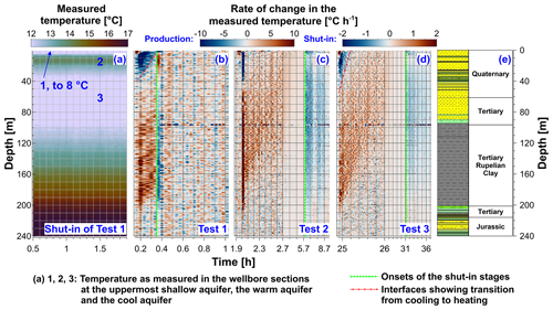
Figure 4Steady state temperature profiling as measured in the shut-in stage of the first artesian flow test (a) and the rate of change in the measured temperature within the studied time windows of the present tests (b–d). The shallow aquifer down to 5 m, the warm aquifer down to 40 m as well as the cool aquifer down to 100 m were shown in the temperature profiling, respectively, and the colour scale was confined from 12 to 17 °C for emphasizing the three aquifers (1–3, a). The positive and negative values in (b–d) denoted heating and cooling, respectively. The colour scales ranged from −10 to 10 °C h−1 and from −2 to 2 °C h−1 were applied to the production and the shut-in stages, respectively. The studied time windows were presented in non-linear axes for better visibility of the production stages.
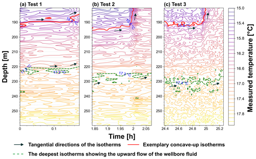
In addition, the isotherms as derived from the DTS-monitored temperature data showed apparent upward movement of the fluid in the wellbore. For instance, the concave-up isotherms of positive slopes at the onset of each production stage indicated that the upper wellbore sections were gradually heated up by the warmer upward flow when the test time proceeded (Fig. 5). By assessing the slopes of the isotherms, the deepest isotherms showing the upward movement of the wellbore fluid were located at the depth of 230 m, which was considered to be the lower limit of the wellbore section for the inflow of the artesian fluid. Such depth corresponded to the bottom of the Jurassic sand strata (Fig. 4e). In short summary the artesian aquifer was confined to the depth interval from 220 to 230 m and to the Jurassic sand strata therein.
Not least, the volumetric rate of the artesian flow as measured at wellhead amounted to 3.6 m3 h−1 (see Fig. 2). The average flow velocity as calculated using this measured flow rate and the cross-sectional areas of the annulus amounted to 199.3 m h−1 above the depth of 98 m, and amounted to 154.2 m h−1 below 98 m, respectively. The wellhead velocity and the volumetric rate of the artesian flow as estimated using the DTS-monitored data amounted to 199 m h−1 and 3.58 m3 h−1, respectively (see Sect. 5.2), being consistent with the wellhead measurements.
4.2 Numerical simulation
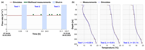
The simulated vertical flow velocities in the annulus between the both casings generally followed a radial parabolic distribution. Therein the maximum value of 285.1 m h−1 in the radial middle of the annulus and the minimum value of 0 at the lateral surfaces of the both casings yielded an average velocity of 197.9 m h−1. The product of this average velocity as well as the cross-sectional area of the annulus of 0.018 m2 (above 98 m) yielded a volumetric flow rate of 3.56 m3 h−1 (Fig. 6a). Moreover, the simulated temperature profiles by the end of the production stages were comparable to the measurements, showing differential values of up to 0.4 °C below the depth of 10 m (Fig. 6b). Such differential value weighted 9 % in the measured increase in temperature of up to 4.5 °C. The differential temperature of the simulates to the measurements above 10 m appeared to be higher than 1 °C. These differential values were due to the fact that the heat transition from the modelled domain to the wellhead atmosphere was not included in the simulation. Although we defined an apparent overpressure of 26.25 kPa to the Jurassic sand so as to match the simulated rates of artesian flow to the measured values, the consistency of the simulated temperature profiles to the measurements would validate the positioning of the artesian aquifer as well as the present numerical model. At least, the measured steady state temperatures from 16.9 to 17.6 °C in the Jurassic sand, together with the simulated flow rates, yielded the temperature profiles comparable to the measurements in the other wellbore sections.
In the following, we further interpret the DTS-monitored temperature data using the output of numerical simulations, so as to reveal the processes of fluid flow in the wellbore and the heat transition in the near-wellbore domain in the present artesian flow tests. The applicability of the DTS-monitored data in characterizing the artesian flow is also discussed.
5.1 Fluid flow and heat transition in the wellbore
In the long-term shut-in ahead of the present tests, the artesian aquifer would have pressurized the annulus between the both casings. When the wellhead valve was opened and the annulus was connected to the atmosphere, the wellhead pressure decreased yielding pressure gradients from the other wellbore sections toward the wellhead and giving rise to the artesian flow. The uppermost wellbore fluid at the shallow aquifer was firstly replaced by the up-flowing fluid from the wellbore section at the warm aquifer (down to 40 m). Thereby, the temperature above the depth of 5 m increased (Fig. 7a, b). Simultaneously, the wellbore fluid at the warm aquifer was replaced by the upward fluid from the cool wellbore section at the lower aquifer (down to 100 m). Therefore, the temperature above 40 m decreased. Concurrently, the cool wellbore section was in turn partly heated up by the fluid from the lower wellbore (Fig. 7b). When the cool wellbore fluid from below 40 m flowed further upward, the uppermost wellbore section underwent cooling (Fig. 7c). As the production proceeded, the artesian aquifer fluid heated up the wellbore sections above 100 m sequentially (Fig. 7d, e). When the production was sustained e.g., for 4 h in Test 2 (Fig. 7e, f), the heat as carried up by the artesian flow was transferred from the annulus between the both casings to a radial extension of approximately 20 cm. During shut-in, the conductive heat transition from the annulus toward the farther subsurface yielded cooling in the wellbore (Fig. 7g). It's noticeable that the wellbore fluid at temperatures of up to 12.2 °C and above the depth of 98 m could flow over a distance of 69.8 m at a velocity of 199.3 m h−1 within the first 0.35 h production stage. This upward flow could replace the fluid initially in the wellbore sections at the uppermost- and the warm aquifers above 40 m, yielding therein an apparent temperature of 12 °C by 0.35 h (Fig. 3a). Thus, the wellbore section from 5 to 40 m was subsequently heated up by the warm aquifer at 14 °C as the first shut-in started (Fig. 4b). Due to this short production stage and the accordingly limited heating by the artesian aquifer fluid, the increase in the wellbore temperature in Test 1 was lower as compared to the cases in the other tests.
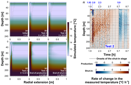
Figure 7Simulated temperature distribution in the near-wellbore domain at studied time instants (a–e, g) and the rate of change in the DTS-measured temperature (f). The colour scale for the simulated temperature were confined to the range from 12 to 17 °C for emphasizing the changes in temperature in the upper wellbore above 40 m (a–e, g). The colour scales from −10 to 10 °C h−1 and from −2 to 2 °C h−1 were applied to the production and the shut-in stages, respectively. The positive and negative values denoted heating and cooling, respectively (f).
5.2 Applicability of the DTS technique in characterizing the artesian flow
The rates of change in temperature as presented in Fig. 4 assisted in positioning the wellbore sections, which had been influenced by the upward fluid flow and the concomitant heat transition. Specifically, the deepest wellbore section showing increases in temperature indicated the upper limit of the possible depth interval confining the artesian aquifer. Moreover, the artesian aquifer would permit therein density-driven convective heat transition (Soboleva, 2018). Such thermal convection could reduce the differential temperature between the upper and lower limits of the artesian aquifer, resulting in a lower thermal gradient as compared to those in the other wellbore sections. Therefore, the depth interval manifesting apparently lower thermal gradient throughout the present tests (Table 1) could indicate the possible position of the present artesian aquifer. In addition, the deepest concave-up isotherms denoting upward movement of fluid at the onsets of productions further helped confining the lower limit of the depth interval for the artesian inflow.
Leaf et al. (2012) had also applied isotherms denoting the upward flow of the warm fluid as injected into a wellbore in the discrete pulse experiment. In their work, moreover, the slopes in the tangent of the isotherms were used estimating the volumetric injection rate. However, the present studied heating process within the wellbore was additionally enhanced by the upward flow of the wellbore fluid besides the contribution of the artesian aquifer fluid. Therefore, the onsets of heating in the wellbore sections below the depth of 45 m were apparently synchronized (Fig. 4b–d). The volumetric rate of the artesian flow as estimated using the isotherms in these wellbore sections amounted up to 30.4 m3 h−1 in contrast to the wellhead measurements of 3.6 m3 h−1. Instead, we estimated such flow rate by applying the depth-time relation as shown at the interfaces, which indicated the transition from cooling to heating above the depth of 40 m (Fig. 4b, d). These interfaces were chosen because the transition here was only induced by the upward flow of the underlying warm wellbore fluid, which was driven by the artesian aquifer fluid. The slopes in the linear depth-time curves representing these interfaces read approximately 199 m h−1, which indicated the flow velocity of the wellbore (artesian) fluid. The so estimated flow velocity, together with the cross-sectional area of 0.018 m2 of the annulus, yielded flow rates of about 3.58 m3 h−1 showing consistency to the wellhead measured values.
In the present study we implemented a series of artesian flow tests in the ATES research wellbore Gt BTrKoe 1/2021 (Berlin, Germany), in the effort to position an artesian aquifer as well as to analyse the artesian flow-induced heat transition in the wellbore using the DTS-monitored temperature profiles. Such monitored temperature profiling revealed the increase in the wellbore temperature of up to 4.5 °C by the artesian flow as well as the recovery in the wellbore temperature at the end of the shut-in test stages. The rate of change in temperature at depths, the thermal gradient as well as the isotherms as derived from the DTS-measured data permitted confining the artesian aquifer to the depth interval from 220 to 230 m. The interface showing the transition from cooling to heating in the wellbore sections above the depth of 40 m enabled estimating the artesian flow rate, which accorded with the wellhead measurements. The wellhead measured flow rate of 3.6 m3 h−1 assisted in establishing a numerical model for evaluating the artesian flow, and the model was validated by the consistency of the simulated temperature profiles in the wellbore to the DTS measurements. The numerical simulation visualized the processes yielding the changes in temperature in the wellbore sections at, e.g., the uppermost shallow aquifer, the warm aquifer down to 40 m and the cool aquifer down to 100 m, respectively. DTS-based monitoring and analyses in conjunction with numerical modelling enabled determining the flow velocity, the flow rate, the depth interval of inflow as well as the profiles of transient flow velocity, etc. Therefore, the present work would be referrable for the studies using distributed temperature sensing technique in the practice of geothermal energy exploitation, gas and petroleum engineering as well as CO2 sequestration and storage.
The DTS-monitored temperature data and the numerical model as presented in this manuscript are available at GFZ.
LP conducted the formal analyses of the DTS data, the numerical simulation and the writing. LV conceptualized and organized the artesian flow tests and contributed to writing. GB supervised the present study. SK, AS and GB validated the results and contributed to funding acquisition.
The contact author has declared that none of the authors has any competing interests.
Publisher's note: Copernicus Publications remains neutral with regard to jurisdictional claims made in the text, published maps, institutional affiliations, or any other geographical representation in this paper. While Copernicus Publications makes every effort to include appropriate place names, the final responsibility lies with the authors.
This article is part of the special issue “European Geosciences Union General Assembly 2024, EGU Division Energy, Resources & Environment (ERE)”. It is a result of the EGU General Assembly 2024, Vienna, Austria, 14–19 April 2024.
The present work was financially supported by the Federal Ministry for Economic Affairs and Climate Action (BMWK) of Germany with the Grant No.: 03EE4033B and by the European Union's Horizon Europe research and innovation program under the Grant No.: 101096566. We thank Christian Cunow for deploying the fiber optic cable and conducting the DTS monitoring. Constructive discussions with Ben Norden, Simona Regenspurg and Claire Bossennec are acknowledged.
This research has been supported by the Bundesministerium für Wirtschaft und Klimaschutz (grant no. 03EE4033B) and the Horizon 2020 (grant no. 101096566).
The article processing charges for this open-access publication were covered by the Helmholtz Centre Potsdam – GFZ German Research Centre for Geosciences.
This paper was edited by Johannes Miocic and reviewed by Johannes Miocic and one anonymous referee.
Blöcher, G., Regenspurg, S., Kranz, S., Lipus, M., Pei, L., Norden, B., Reinsch, T., Henninges, J., Siemon, R., Orenczuk, D., Zeilfelderf, S., Scheytt, T., and Saadat, A.: Best practices for characterization of high temperature-aquifer thermal energy storage (HT-ATES) potential using well tests in Berlin (Germany) as an example, Geothermics, 116, 102830, https://doi.org/10.1016/j.geothermics.2023.102830, 2024.
Doonechaly, N. G., Reinicke, A., Hertrich, M., Plenkers, K., Obermann, A., Fischli, F., Maurer, H., Wiemer, S. and Giardini, D.: Multiphysics monitoring of cementation operation: implications for wellbore integrity and hydrogeological characterization, Environ. Earth Sci. 83, 146, https://doi.org/10.1007/s12665-024-11451-2, 2024.
Leaf, A. T., Hart, D. J., and Bahr, J. M.: Active thermal tracer tests for improved hydrostratigraphic characterization, Ground water, 50, 726–735, https://doi.org/10.1111/j.1745-6584.2012.00913.x, 2012.
Lipus, M. P., Reinsch, T., Tobias B. Weisenberger, T. B., Kragset, S., Stefánsson, A., and Bogason, S. G.: Monitoring of a reverse cement job in a hightemperature geothermal environment, Geotherm. Energy, 9, 5, https://doi.org/10.1186/s40517-021-00187-y, 2021.
Liu, J. R., Han, Y. H., Jia, Q. S., Zhang, L., Liu, M., and Li, Z. G.: Oil-water flowing experiments and water cut range classification approach using distributed acoustic sensing, Spe. J., 29, 1238–1253, https://doi.org/10.2118/218389-PA, 2024.
Norden, B., Virchow, L., Fuchs, S., Mitzscherling, J., Gravendyck, J., Zimmer, M., Saadat, A., and Sect. Geomorphology, Sediment Lab: The explorational drilling Gt BTrKoe 1/2021 in Berlin Adlershof, Germany – field data and measurements, GFZ Data Services [data set], https://doi.org/10.5880/GFZ.4.8.2023.006, 2023.
Piekarski, J. K., Norden, B., Fuchs, S., Regenspurg, S., Virchow, L., Blöcher, G., Kranz, S., and Saadat, A.: Geothermal district heating in Berlin: an ATES field study in Berlin-Adlershof, Proc., EGC, 2022, Berlin, Germany, https://gfzpublic.gfz-potsdam.de/pubman/item/item_5022818 (last access: 24 June 2024), 2022.
Shetty, R., Sharma, J. and Tyagi, M.: Experimental study on sand detection and monitoring using distributed acoustic sensing for multiphase flow in horizontal pipes, SPIE J., 29, 1045–1060, https://doi.org/10.2118/218005-PA, 2024.
Soboleva, E. B.: Density-driven convection in an inhomogeneous geothermal reservoir, Int. J. Heat Mass Transf., 127, 784–798, https://doi.org/10.1016/j.ijheatmasstransfer.2018.08.019, 2018.


