 | 02 Oct 2019
Lab scale salt caverns – first results on construction and investigation techniques
Martin Zimmer
Rik Tjallingii
Salt caverns from solution mining in bedded or domal saline structures are of increasing importance as temporary subsurface storage space to buffer fluctuating renewables and secure a stable energy supply. To assure the integrity of caverns during operation and long term abandonment, knowledge of geochemical rock–water interactions in the transition zone between cavity and salt rock is necessary. Due to the inaccessibility of cavern walls, a set of lab-based experiments were performed in hand-sized specimens by creating cm-sized cavities using fresh water injection and brine removal. The experimental simulations proved challenging and vacuum pressure tests revealed frequent leakage subsequent to borehole preparation. The samples were cut to expose the formed cavity and its margin. Micro X-ray Fluorescence mapping was employed to obtain information on element distributions and showed a clear separation between Na, Mg and K salt layers. XRF mapping represents a suitable technique to track spatial mineralogical changes related to rock-fluid interaction in salt rocks. Fluorescent liquids were used to visualize potential fluid pathways. First results show that these methods are promising in detecting geochemical changes and their extent and are, thus, useful tools in unravelling geochemical processes related to marginal areas of cavernous structures in salt deposits based on lab-scale simulations.
- Article
(4655 KB) - Full-text XML
- BibTeX
- EndNote


Due to the unique characteristics of salt deposits – low permeability, high water solubility and the visco-plastic behaviour – the construction of technical caverns is commonly practiced to create voluminous storage space (e.g. Durup, 1994; Berest et al., 2001; Lux, 2009; Brouard et al., 2001). Preferably, they are located in homogeneous rock salt deposits. However, salt formations often contain intercalated layers or lenses of minerals with deviant behaviour in terms of rock integrity and solubility, such as anhydrite layers, potash beds or clay lenses (e.g. Braitsch, 1962; Warren, 2016).
Water and solutions in disequilibrium with the solid salt wall result in a reactive zone with complex solution-precipitation processes that continuously change the effective porosity along the periphery of the cavern (Durie, 1964; Heekeren et al., 2009; Röhr, 1981; Voigt et al., 2001). Especially in the presence of soluble or reactive mineral layers, this might influence the integrity of cavernous structures. Detailed knowledge on the interaction between mineral dissolution and recrystallization and potential changes in porosity in the vicinity of caverns is, therefore, crucial in order to estimate the propagation potential of salt solution processes.
Most processes will occur along the cavern wall where fluid and solid phases interact. Due to the inaccessibility of storage caverns, alternatives to in situ observations need to be considered. A common way to respond to remoteness or isolation of a setting of interest is the experimental simulation on laboratory scale.
Against this background, we tested the possibility of lab-scale solution mining to form caverns on different saliniferous rock samples. The experience on the construction of lab caverns are reported here together with promising results on investigative methods to monitor changes along the marginal area of the cavern wall.
Samples were obtained in a potash mine located within the central German Werra-Fulda mining district. Here, Zechstein evaporites of the Werra Formation (Z1) are deposited on top of siliciclastic Permian Rotliegend rocks. The Werra Formation is dominated by rock salt with two intercalated potash seams mainly consisting of hard salt (for details see Strauch et al., 2018). Hard salt is a mining term for salt rocks that are generally harder to drill than rock salt with a main mineral composition of halite (NaCl), sylvite (KCl) and kieserite (MgSO4⋅H2O).
Large, mainly irregular hand specimens with up to 40 cm edge length were sampled along the Middle Werra rock salt and the hard salt horizon of Seam Hessen. Care was taken to obtain massive, undisturbed and non-fractured salt blocks.
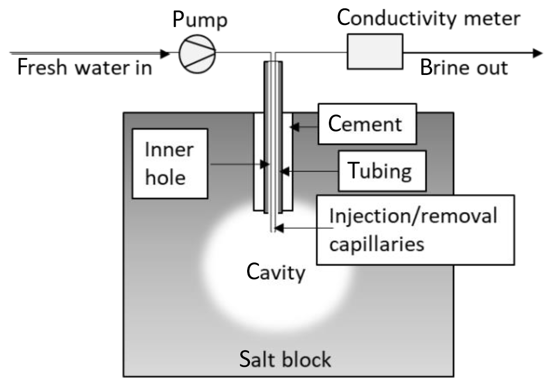
The salt blocks were placed under air-conditioned lab environment at ambient humidity. For cavern construction by solution mining, a hole of 12 mm diameter and 35 mm length was drilled centrally into the block. The hole was filled with a mixture of saline water and magnesia cement – a composite commonly used to fixate pipes in large bore holes during underground salt exploration mining. A tubing was centrally encased into the concrete. After hardening, a further small borehole was set through the tubing to create an initial cavity (diameter of 6.3 mm, length of 45 mm) for leaching. Pressure tests were performed before and after drilling the small borehole. For this, the tubing was temporarily fitted to a vacuum pump and pressure sensor. After evacuating the borehole volume, pressure increase with time was recorded.
Following this, two capillaries were inserted into the large tubing and attached with leak-tight stainless steel fittings.
To simulate salt solution mining, one capillary was utilized to supply deionized water into the cavity, the other served as exit for the resulting brine. A HPLC pump was applied to assure a constant inflow pump rate. The effluent brine was analysed for conductivity and the retained volume was measured (Fig. 1).
Subsequent to the solution mining, the salt block was cut open directly through the expected cavernous structure using a band saw. The sliced salt block was used to test different analytical techniques.
Micro X-ray Fluorescence mapping was employed to obtain information on element distributions using a Bruker M4 Tornado. An area of about 12 cm2 was mapped covering the marginal structure of the cavern. The analyses were performed every 50 µm on the rock surface to provide information on the element distribution of Na, Mg, Al, Si, S, Cl, K, Ca, Fe, Br, and Sr. Additional tests were performed using the sodium fluorescein technique with a dye concentration of 0.1 % visible by a UV light source of 395 nm wavelength (Walker, 1986).
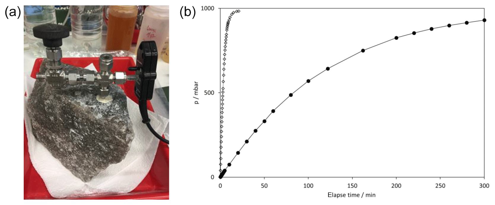
Figure 2(a) setup of vacuum pressure tests on salt rock sample. (b) typical pressure increase with time. Closed symbols show pressure course in the cemented tubing, open symbols show fast pressure increase after drilling through the cemented tube to emplace injection capillaries. Test were performed before leaching.
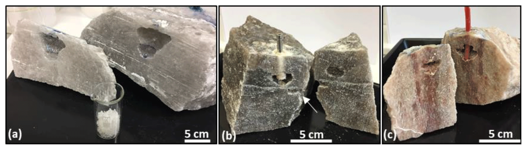
Figure 3Small-scale caverns in rock salt (a, b) and hard salt (c). The tubing in rock salt is cemented, for hard salt an alternative epoxy closure was used. In (b) the arrow indicates the “alternative” fluid pathway out of the rock.
3.1 Preparation of a borehole seal
The preparation of a leak-tight cemented borehole seal was the first prerequisite for a subsequent solution mining. In rock salt samples the cement seals were successfully formed, however, borehole sealings in hard rock samples from the potash seam frequently resulted in the formation of porous and perforated cement after hardening. This indicates, that the liquid phase of the sealing cement rapidly percolated into the surrounding rock mass, causing an overly shrinking cement and the formation of small pores in the transition between rock and cement or even within the cementing material. In turn, this resulted in leakage along the borehole closure and, thus, frequently prevented cavern formation within the rock block. To avoid effects on fluid percolation during cementing, an alternative borehole closure was successfully created by using epoxy resin. Still, preferential fluid pathways developed along weak sites which were always given along the contact zone between solid salt rock and cementing material. Adding to that, less dense inflowing fresh water is always positioned in the upper part of the cavern. With its high solubility potential, an upward leaching of the salt rock is unavoidable. In technical caverns, this is prevented by using a low-density inert blanket fluid (e.g. N2 or oil), placed on top of the cavern fluid. It protects the roof from extensional dissolution or fluid escaping along the critical zone of the well opening (Warren, 2016). On the lab scale, no such blanket was used and, as illustrated in Fig. 2b and c, the cavern growth was always upwards from the initial injection point. For a successful cavern construction, a sufficiently low initial injection position was, therefore, crucially required.
3.2 Pressure tests
To verify the integrity of salt block and cement regarding gas tightness, vacuum pressure tests were performed before solution mining. The borehole was evacuated using a vacuum pump and the subsequent pressure increase was detected using a pressure sensor (Fig. 2). Tests on dry samples show, that none of the investigated salt blocks were gas tight and, in addition, the cement sealing was also not absolutely gas tight. In Fig. 2, the pressure progression after evacuation of the cemented tubing is shown. The pressure rose to air pressure within approximately 5 h. When the drill hole was extended for about 1 cm into the dry salt block, the test was repeated. Now, the pressure increased to ambient conditions within 30 min. This indicates, that the dry rock already holds microcracks or other irregularities along which gas migration easily occurred. Further fracturing was probably caused by drilling of the injection borehole and explains the fast pressure increase in the second pressure test.
For the creation of cavities by solution mining these vacuum pressure tests were a first indicator of the expected leakage rate during fresh water injection. The faster the pressure increased the more likely leakage occurred during solution mining.
3.3 Lab-scale salt solution mining
3.3.1 Solution mining in rock salt
A successful solution mining in a rock salt sample (a) that created a cavern of about 15 cm3 (Fig. 3a) was performed for about three hours by pumping of 1 cm3 water per minute into the cavity. Within 200 min, 200 cm3 water were injected and 175 cm3 brine were produced. The brine had a bulk conductivity of 206 mS cm−1 which relates to a salinity of 144 kg m−3 and implies that 29 g salt were removed. Assuming a pure halitic composition with a density of 2.16 g cm−3, a salt volume of 13.4 cm3 was removed, forming a cavern with similar volume. This is in agreement with the excavated void (Fig. 3a). Approximately 25 cm3 of the inflow fresh water could not be recovered and was likely to be percolated into the salt body.
A second, similar experiment in rock salt (b) was performed but showed different results. The experimental duration was 180 min. The recorded outflow of brine in the first hour was 30 cm3, in the second hour 15 cm3 were regained and in the third hour only 5 cm3 could be recovered. 42 cm3 brine were leaked from the side of the salt block and indicate the existence of a pre-existing and re-opened disruption now used as fluid pathway (Fig. 3b). The bulk brine conductivity was 274 mS cm−1 and relates to 18 g halite removed by leaching which equals to a volume of 8.3 cm3 pure halite. This is in good agreement with the void formed.
Even though both salt bodies had a similar halitic mineral composition, the grain size and crystallinity differed. While sample (a) comprised a massive fine-grained rock body, (b) was of coarse-grained mineralogical appearance and, therefore, presumably of higher fluid permeability along crystal boundaries.
3.3.2 Solution mining in hard salt
Only one of five experiments on hard salt samples proved successful. Even though blocks of up to 50 cm edge length which were superficially intact were used, leakage occurred shortly after solution mining was started. Brine was rarely recovered, it mostly percolated through the rock, either upward, re-appearing around the borehole closure, or along planar or linear structures through the apparently tight salt block. The cavern shown here (Fig. 3c) is the result of 100 cm3 fresh water inflow. However, only 17 cm3 brine discharge could be recovered. To trigger brine outflow, fresh water was introduced with varying flow rates, also suction of the brine at the exit was performed. However, most of the inflowing water seemed to percolate into the rock or exited the block via alternative pathways, mainly upward, along the borehole closure. Here, a wetted area of about 15 cm diameter was observed shortly after solution mining started. Nevertheless, a cavity of approximately 4 cm3 could be created.
All solution mining experiments proceeded differently, but they all had a considerably lower volumetric brine output in comparison to fresh water input in common.
Several leaching experiments had to be abandoned due to strong leakage through the side walls of the salt block or the top area around the borehole cement.
3.4 X-ray fluorescence measurements
Element distribution obtained by XRF scanning are indicative for mineral compositions. The XRF mapping results revealed a clear separation between Ca, Na, Mg and K-rich minerals which can be associated with main salt minerals assemblages of the hard salt samples. Ca-rich salt minerals were attributed to anhydrite (CaSO4), Na-, K- and Mg-rich mineral aggregates were associated to halite (NaCl), sylvite (KCl) and kieserite (MgSO4⋅H2O), respectively. These are the main constituents of the investigated “kieseritic hard salt” samples, typically occurring in the seams of the Werra-Fulda Zechstein basin.
Figure 4b shows the elemental distribution along the cavity rim of the hard salt sample after solution mining with deionized water. A distinct layering and separate Na-, K- and Mg-rich mineral phases was visible, presenting the layering typically found in bands of the upper potassium-rich seam Hessen where the sample originates from. Noteworthy is the clear visual separation of a Mg-rich rim surrounding sylvite. With respect to the leaching process, no mineral dissolution/precipitation in the vicinity of the cavity was observed.
The open void was then impregnated with 2 cm3 of an undersaturated (5 N) NaCl solution for several days and the XRF mapping of the elemental distribution at the cavity rim repeated (Fig. 4d). Now, secondary crystalline halite-dominated overgrowth within the cavity area and at the edges of the void was visible (Fig. 4c). Also an extensive spreading of the Na-rich phase around the cavity was detected. The outer rim of the fluid migration front was Mg-rich, the K-rich phase was less influenced or intermingled with the Na-rich phase.
Even though the clear indication for water–rock interaction in the marginal cavern area was possibly only superficial, it shows that XRF mapping represents a suitable technique to track spatial mineralogical changes related to rock-fluid interaction in salt rocks.
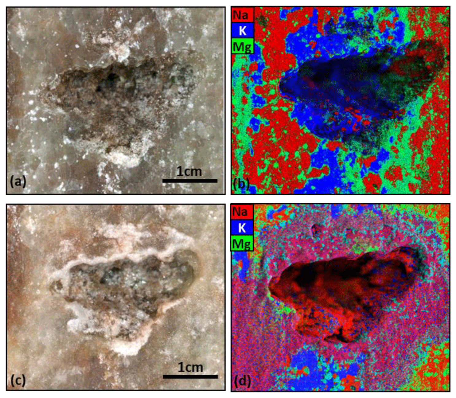
Figure 4Micro XRF mapping of a cavernous rim structure. (a) photo image and (b) XRF image of the area after initial leaching of the closed salt block. (c) photo image and (d) XRF map after impregnation of the open cavity with 5 N NaCl solution.
3.5 UV fluorescence measurements
Sodium fluorescein is soluble in water and, therefore, an easily added reagent to trace fluid pathways. As a preliminary test, sodium fluorescein-containing water was injected into an open borehole next to a lab cavern in a rock salt sample (Fig. 5).
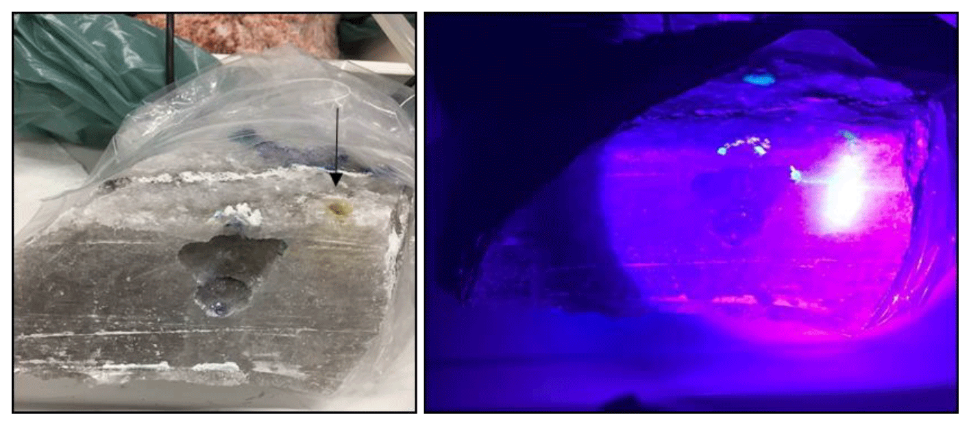
Figure 5Injection of fluorescein-labelled water in a borehole next to the cavern (arrow). UV-lamp was used to visualize the migration of fluid.
Using UV light, the distribution of the aqueous phase was visualized and revealed that the liquid phase migrated evenly to the side with the exceptional migration along a subhorizontal bedding plan where the liquid reached the cavity.
The technique is easy to apply and promising if knowledge on fluid pathways and extend of migration is needed.
The formation of caverns by salt solution on lab scale is challenging for several reasons. The prerequisite for a successful operation is undisturbed and unfractured blocky and massive rock samples. The preparation of a tight borehole seal is important for cavern creation. Naturally, preferential fluid pathways develop along weak sites which are always created artificially along the contact zone between solid salt rock and cementing material. In technical caverns the roof is insulated from extensional dissolution or fluid escaping by adding a blanket. For lab-scale cavern construction, however, the implementation of such a blanket is not feasible. Therefore, a deep (below the centre of the block) initial injection position should be chosen.
The construction of lab-scale caverns is a time consuming process and needs to be adapted to individual sample settings. Therefore, each solution mining is unique and it is not possible to produce an overall valid “recipe” on lab-scale cavern construction. However, the technical implementation of lab-scale caverns gives a good overview on the rock behaviour and the challenges anticipated in inhomogeneous rock compositions.
For the visualization of water–rock interaction in the marginal cavern area several techniques have been tested. The mapping of element distribution with XRF represents a suitable technique to track spatial mineralogical changes related to rock-fluid interaction in salt rocks. It shows spatial changes of major element distributions at the cavern rim related to salt remineralization. Also, the utilization of fluorescent liquids is helpful for the identification of fluid pathways.
Without applying a confining pressure, salt blocks of decimetre size investigated here are only limited suitable for the creation of cavernous structures. Tests on gas tightness indicate a strong permeability of the salt blocks, due to micro-fracturing during sampling and handling. To simulate solution mining in salt rocks and to investigate marginal geochemical processes, the creation of cavernous structures should be done in situ or on a larger scale by simultaneously applying a confining pressure to the sample. To test fluid rock interaction on the small lab-scale, a less laborious design might result in similar outcome. The investigation on similar rock types using alternative techniques, such using core samples under confining pressure will be envisaged in further studies.
The data are accessible in the data repository of the GFZ at: http://gfzpublic.gfz-potsdam.de/pubman/ (last access: 28 September 2019).
The lab scale simulations were conducted by BS and MZ. The XRF mapping was performed by RT.
The authors declare that they have no conflict of interest.
This article is part of the special issue “European Geosciences Union General Assembly 2019, EGU Division Energy, Resources & Environment (ERE)”. It is a result of the EGU General Assembly 2019, Vienna, Austria, 7–12 April 2019.
We thank the staff of the potash mine for their great support during sampling. This study is part of the project ProSalz and we gratefully acknowledge the financial support of the BMBF within the framework program Geo:N – geoscience for sustainability under grant no. 03G0873A.
The article processing charges for this open-access publication were covered by a Research Centre of the Helmholtz Association.
This paper was edited by Antonio Pio Rinaldi and reviewed by Julia Arndt and one anonymous referee.
Berest, P., Bergues, J., Brouard, B., Durup, J. G., and Guerber, B.: A salt cavern abandonment test, Int. J. Rock Mech. Min., 38, 357–368, 2001.
Brouard, B., Bérest, P., and de Greef, V.: Salt Permeability Testing- The Influence of Permeability and Stress on Spherical Hollow Salt Samples, Part 1 SMRI Research Report RR2001-8, 2001.
Braitsch, O.: Entstehung und Stoffbestand der Salzlagerstätten, in: Mineralogie und Petrographie in Einzeldarstellungen, edited by: Engelhardt, W. V. and Zemann, J., Bd. 3, Springer Verlag, Berlin, 232 pp., 1962.
Durie, R. W.: Mechanism of the Dissolution of Salt in the Formation of Underground Salt Cavities, Soc. Petrol. Eng. J., IV, 183–190, 1964.
Durup, J. G.: Long-Term Tests for Tightness Evaluations with Brine and Gas in Salt (Field-Test No. 2 with Gas), SMRI Research and Development Project Report, Proc. S.M.R.I. Fall Meeting, September 1994, Hannover, Germany, 1994.
Heekeren, H. V., Bakker, T., Duquesnoy, T., Ruiter, V. D., and Mulder, L.: Abandonment of an extremely deep Cavern at Frisia Salt, Solution Mining Research Institute Technical Conference, 27–28 April 2009, Krakow, Poland, 1–13, 2009.
Lux, K.-H.: Design of salt caverns for the storage of natural gas, crude oil and compressed air: Geomechanical aspects of construction, operation and abandonment, in: Underground Gas Storage: Worldwide Experience and Future Development in the UK and Europe, edited by: Evans, D. J. and Chadwick, R. A., Geol. Soc. London, Spec. Pub., 313, 93–128, 2009.
Röhr, H. U.: Lösungsgeschwindigkeiten von Salzmineralen beim Ausspülen von Hohlräumen im Salz, Kali und Steinsalz, 8, 103–111, 1981.
Strauch, B., Zimmer, M., Zirkler, A., Höntzsch, S., and Schleicher, A. M.: The influence of gas and humidity on the mineralogy of various salt compositions – implications for natural and technical caverns, Adv. Geosci., 45, 227–233, https://doi.org/10.5194/adgeo-45-227-2018, 2018.
Voigt, W., Voigt, H., and Jockel, A.: Lösungsprozesse im carnallitischen Salzgebirge – geochemische Modellierung und praktische Bedeutung. Exkursionsführer und Veröffentlichungen der GGW, Berlin, 6.23, 2001.
Walker, D. A.: A fluorescence technique for measurement of concentration in mixing liquids, J. Phys. E, 20, 217–223, 1986.
Warren, J. K.: Evaporites, A Geological Compendium, Second Edition, Springer International Publishing, Switzerland, 2016.