 | 17 Mar 2023
CHENILLE: Coupled Behavior Understanding of Faults: from the Laboratory to the Field
Audrey Bonnelye
Pierre Dick
Marco Bohnhoff
Fabrice Cotton
Rüdiger Giese
Jan Henninges
Damien Jougnot
Grzegorz Kwiatek
Stefan Lüth
The understanding of coupled thermo-hydro-mechanical behaviour of fault zones or in naturally fractured reservoirs is essential both for fundamental and applied sciences and in particular for the safety assessment of radioactive waste disposal facilities. The overall objective of the CHENILLE project is to better understand the physical processes resulting from thermal and hydraulic loading in a small fault zone in a highly consolidated shale formation. Consequently, a thermally controlled in-situ fluid injection experiment is intended to be performed on a strike-slip fault zone outcropping at the Tournemire/France Underground Research Laboratory (URL). A heating system has been installed around the injection area to enable a precise and controlled incremental increase of the thermal load. Different monitoring systems are designed to measure the seismic and aseismic deformation induced either by thermal and/or by hydraulic loading. The seismic monitoring system is composed of Acoustic Emission (AE) and broadband seismic sensors enabling monitoring of seismic fracturing processes down to sub-decimetre scale as well as slow deformation processes. Furthermore, we are about to install an injection chamber allowing to perform a controlled gaz injection test. The injection borehole will also be partly equipped with fiber optics in order to measure temperature in a distributed manner in the borehole. Time-lapse active seismic surveys are scheduled for before and after the experiment to image the structural network but also to detect the appearance of new structures triggered from the hydro-thermal pressurization of the fault as well as eventual changes in the velocity field.
- Article
(4328 KB) - Full-text XML
- BibTeX
- EndNote


Numerous multidisciplinary studies have improved the understanding of hydro-mechanical behaviour of the geological subsurface, with immanent implications towards mitigating anthropogenic seismic hazard in the context of developing geothermal reservoirs (Kwiatek et al., 2019; Amann et al., 2018), or for the safe storage of radioactive waste (Armand et al., 2017) and carbon dioxide (Guglielmi et al., 2021), as well as for hydrocarbon extraction. However, due to the technical challenges involved, coupling these efforts to include the influence of temperature changes has so far been set aside despite its fundamental relevance.
In addition to its societal relevance, this topic is of paramount importance to improve the understanding of the coupled Thermo-Hydro-Mechanical (THM) behaviour of geological reservoirs (both for storage and production) and along active plate-bounding fault zones. One method used by the Earth science community to understand THM processes of reservoirs is to build large-scale field approaches monitored through geophysical methods. However, these non-intrusive geophysical technologies generally provide images related to the spatial distribution of physical properties which rarely allow to decouple the processes involved directly : geophysical monitoring in general is a key topic for many purposes related to geosequestration (Davis et al., 2019). In this respect, laboratory experiments can be conducted at various pressure-temperature conditions to identify mechanisms during deformation processes. Unfortunately, as of today, these approaches are still limited to short time scales (between 1 d to a month), very small spatial scale (e.g. sample sizes of the order of centimeter). Moreover, these processes are rarely studied using a joint laboratory and field research approach (e.g. in-situ injection experiment). The here presented research program aims at closing this gap. We here intend to address key questions related to the impact of high temperatures of the rock mass(up to 150 ∘C) on deformation zones as well as fault reactivation processes in the geological underground. We will use the already acquired knowledge of the site in Tournemire/France Underground Research Laboratory (URL) to conduct the Coupled beHavior undErstaNdIng of fauLts: from the Laboratory to the fiEld experiment (CHENILLE) project in order to tackle fundamental questions concerning the thermo-hydro-mechanical behaviour of fault zones in low permeable reservoir rocks.
The principal objectives of CHENILLE are:
-
Generate a profound understanding of the spatiotemporal evolution of temperature and pore-pressure fields caused by induced heating of an intact, damaged and intensely deformed shale formation crossed by a tectonic fault (“fault-heating experiment”).
-
Understand the coupled hydro-thermo-mechanical processes occurring in and around a meso-scale fault in a semi-controlled environment, bridging the knowledge gap between laboratory and field.
-
Develop novel geophysical monitoring techniques and strategies in different scales suitable for highly attenuating material (clay rich rocks) in an URL and under natural conditions, i.e. with a fault zone in place and under high-temperature conditions.
This experiment will allow us to test monitoring methods that have proven their effectiveness in other geological environments and on laboratory scale, and to illustrate the influence of temperature on natural geological structures under representative in-situ conditions.
The experiment consists of stimulating a fault zone by injecting gas in its core and simultaneously heating or cooling the injection zone. Optimized geophysical monitoring methods have been installed for different scales and resolutions around the stimulation zone. These methods had been either tried or tested in other types of materials (combination of pneumatically driven seismic impact sources for application along the tunnel surfaces and single well imaging (SWI) tools for borehole seismic exploration, passive acoustic emission (AE) monitoring methods based on the use of acoustic/high-frequency sensors), or based on more recent methods (optical fibres for temperature measurement), but never in our type of environment combining thermal and hydraulic stimulation in clay rich rock.
The in-situ scale tackled here bridges the lab scale with its controlled boundary conditions with the field scale along plate-bounding fault zones where processes occur entirely out of control. CHENILLE thus allows to transfer knowledge gained at either end of the scale to derive a better understanding of deformation processes under realistic in-situ conditions. Finally, this study will allow to obtain results from controlled experiments to produce new methods or hypotheses to be implemented and investigated in the field. Conversely, observations in the field will potentially produce new hypotheses that will be in turn tested by controlled experiments. The objective of the present paper is to provide a detailed description of the CHENILLE experiment to give an overview of the combination of geophysical measurements that we are intending to perform.
Faults are mechanical discontinuities in the crust where deformation is localized and where elastic energy is released both seismically and aseismically (Ben-Zion and Sammis, 2003; Faulkner et al., 2008; Kaduri et al., 2017; Romanet et al., 2018). This denomination includes features with a size that may vary from meter scale (the so-called “meso-scale”) up to hundreds of kilometers (field scale along plate bounding tectonic faults). Due to their complex structure and mechanical behavior, their study requires a wide range of combined tools such as geomechanics, structural geology, geophysics, geodesy or geochemistry. Similarly, controlled experiments in the laboratory on specimens of cm-scale can be performed, allowing a better understanding of the physical mechanisms responsible for the failure, from the preparatory phase to the post rupture phase (Bonnelye et al., 2017a; Geng et al., 2017; Schuster et al., 2021). These approaches are very complementary and allow studying relevant processes and parameters in detail and with the option to repeat experiments and control the boundary conditions. Nevertheless, the question remains if up-scaling to meso- and field scale facilitates better understandingof the underlying processes controlling reactivation of faults in geological reservoirs and rupture initiation of large earthquakes along fault zones.
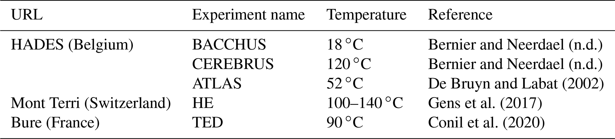
Over the past decades, numerous hydraulic stimulation experiments have been carried out in mesoscale in mines and URLs around the world (e.g., Kwiatek et al., 2019; Hadermann and Heer, 1996; Kneafsey et al., n.d.; Zang et al., 2017; Baisch, 2002). It is commonly accepted that these experiments are very important towards understanding processes governing induced seismicity for industrial applications such as geothermal energy, shale gas exploitation, subsurface gas storage and nuclear waste disposal. However, for technical reasons, most URLs are at shallow depth and the range of pressure and temperatures investigated in the frame of the experiments are low. Therefore, they are not representative of the conditions encountered in natural seismogenic zones, nor for industrial applications such as energy storage (geothermal), or conditions that can be encountered in the frame of nuclear waste disposal. For that reason, and even though laboratory experiments show that temperature plays a major role in the mechanical behaviour in clay rich materials, this parameter is rarely considered in mechanical models of fault zones. In spite of this, some in-situ experiments have been developed, allowing the monitoring of fluid potential overpressure under limited temperature conditions in unfractured zones (De Bruyn and Labat, 2002; Bernier and Neerdael, 1996). These experiments show that an increase of temperature, even if small, can lead to an increase of several bars in pore pressure, which could be of major importance for a critically stressed fault or in the frame of nuclear waste disposal safety.
Table 1Table presenting previous heating experiments performed in URLs dedicated to research on clay rich materials in western Europe.
Consequently, the project CHENILLE aims at studying the THM processes in the frame of a French German collaboration (the experiment has been delayed due to the pandemic situation and will take place in winter 2023).
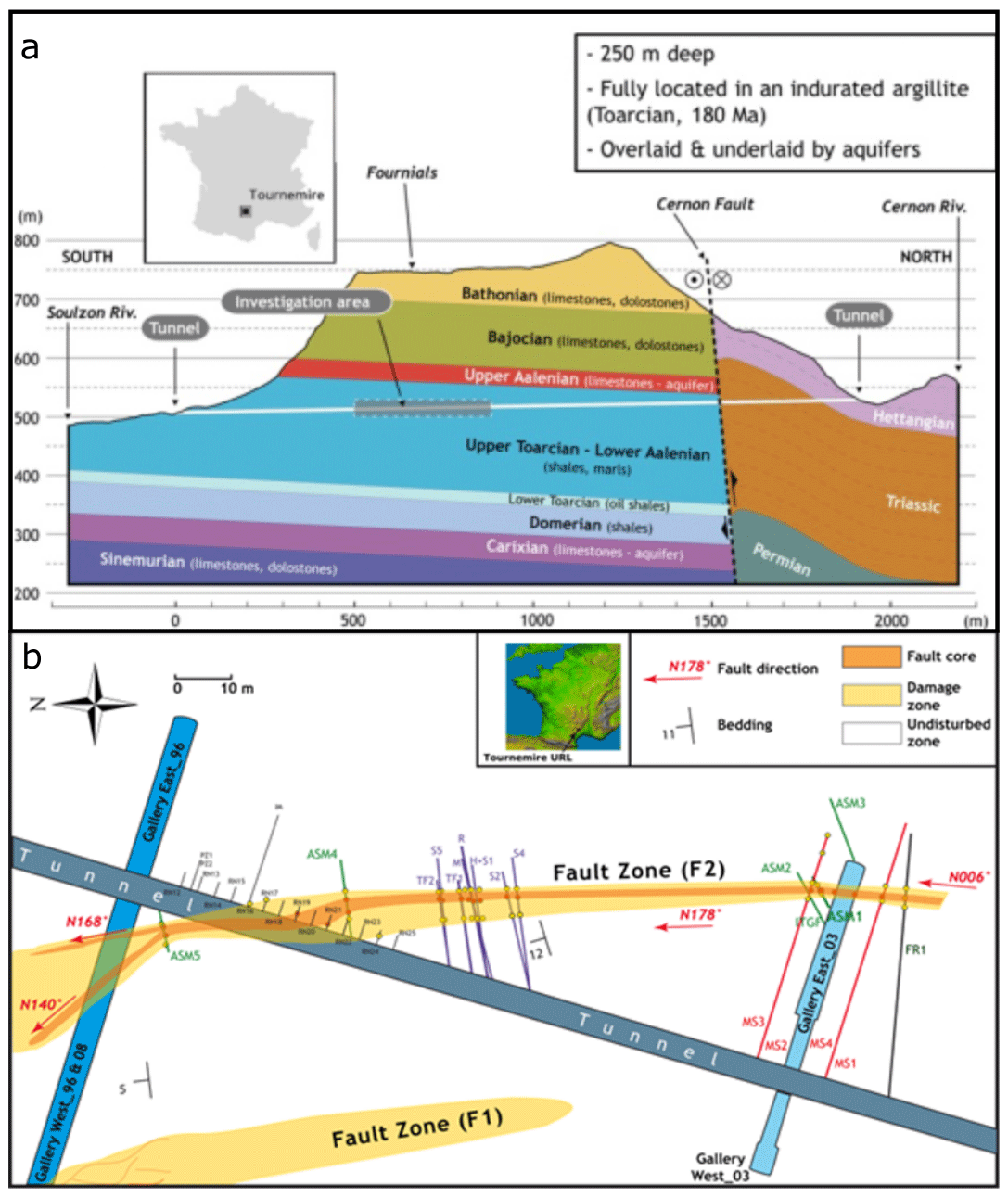
Figure 1Overview of the Tournemire URL (after Lefèvre et al., 2016). (a) Cross section of surroundings of the tunnel; (b) Simplified map of the Tournemire URL. The spatial distribution of the fault zones was determined from borehole logging and geological mapping from the galleries' floor, walls, and roof. The three main components of the fault zones are: the fault core (represented in orange), the damage zone (represented in yellow), and the intact protolith (represented in white). The fault core corresponds to the area of the fault zone where the majority of the displacement has taken place and includes gouge, cataclasites, kink bands, and subvertical schistosity. The damage zone forms a transition zone from the fault core to the protolith. The damage zone includes small faults, brittle fractures, and veins. The protolith denotes the non-deformed or non-fractured rock,non fractured (host) rock. The boundary between the protolith and damage zone is gradual while the boundary between the damage zone and fault core is sharp.
3.1 Geological setting and structural description of the area of interest
The field test is located in the Tournemire URL (S France) owned by IRSN (French Institute for Nuclear Safety). The URL is composed of a 1.9 km long former old railway tunnel (excavated 135 years ago) and six other galleries (excavated between 1996 and 2008). The Tournemire URL is a key infrastructure enabling to study and understand the confining properties of shale rocks and the performance of certain components of a nuclear waste repository (engineered barrier systems or EBS) to provide an independent and robust technical assessment of France's future deep geological disposal facility for radioactive waste.
The old railway tunnel crosses a Lower Jurassic shale formation (Toarcian, 180 My) that has been extensively studied over the past 30 years in terms of physical properties, mechanical behaviour, chemical composition etc. (Boisson et al., 2001; Bonin, 1998; Matray et al., 2007; Dick et al., 2016; Moreno et al., 2018; Niandou et al., 1997; Bonnelye et al., 2017b; Masri et al., 2014). The Tournemire shale rock has the particularity to be imbedded with faults and fractures of different sizes that extend from the surface (sedimentary cover) to the basement (crystalline). Two minor faults (F1 and F2, see Fig. 1) outcropping in the URL have been extensively studied (Boisson et al., 2001; Bonin, 1998; Matray et al., 2007; Dick et al., 2016; Moreno et al., 2018) and thus offer a unique opportunity to understand under various conditions a well-documented and well-preserved 3D clay-rich fault rock.
The architecture and geometry of these fault zones were determined by small-scale mapping of the galleries' walls and floor and through the geological and geophysical logging of boreholes and core samples (Fig. 1). F1 and F2 have a similar dip and dip-direction varying spatially between 170 to 010∘ N and 60 to 80∘ N (Lefèvre et al., 2016) and are characterized by reverse left-lateral strike slip movement (Peyaud et al., 2006). The F1 fault exhibits a complex array of anastomosed fault surfaces consisting of brittle fractures and ductile shear bands, whereas the F2 fault presents three main architectural elements: a central fault core (FC) which accommodates most of the displacement, a damage zone (DZ) surrounding either side of the FC and a FC-DZ transition zone located on the eastern fault compartment. The F2 FC is 0.5 to 1.7 m thick and consists of thin dark bands of centimetre thick gouge, cataclastic and brecciated rock, as well as subvertical schistosity planes, folds and lenses of less deformed rock (Fig. 2). The damage zone is 3–4 m wide in the hanging wall and 1–2 m wide within the footwall. The damage zones, if formed by a dense network of small faults, fractures, and veins, were completely sealed by crystalline calcite. The FC-DZ transition zone is only visible in the footwall and is 0.5 to 1 m thick. The FC-DZ transition zone presents a well-defined 20–30∘ southward dipping schistosity as well as fractures and veins sealed by crystalline calcite. Bedding planes in the damage zone and undisturbed protolith dip gently towards the North (5–10∘). However, a gradual increase in bedding plane dip can be seen towards the fault core. The boundary between the protolith and damage zone is diffuse, whereas the boundary between the FC, DZ and transition zone is sharp and lined by a thin band of gouge. A dolomitic horizon marker crossed by several boreholes on either side of the fault suggests that the amount of slip perpendicular to strike is roughly 4–6 m while slip along strike is estimated to be between 15 and 30 m.
3.2 Experimental set-up
This THM field test is located at the depth level of the F2 fault at 10 m distance from the northern wall of the Gallery East_03. A view of the borehole setup is shown in Fig. 2, which will host the different monitoring systems that will be installed. The borehole layout consists of four types of boreholes: (i) one injection borehole (BH1) that crosses the entire fault centered and equipped with a hydro-mechanical probe centered along the fault's core; (ii) four heating boreholes (BH2 to BH5) dedicated to host electrical heaters, (iii) 4 boreholes (BH6 to BH9) dedicated to the geophysical monitoring of seismic and aseismic fracturing processes and (iv) 17 boreholes for active seismic imaging (BH10 to BH26).
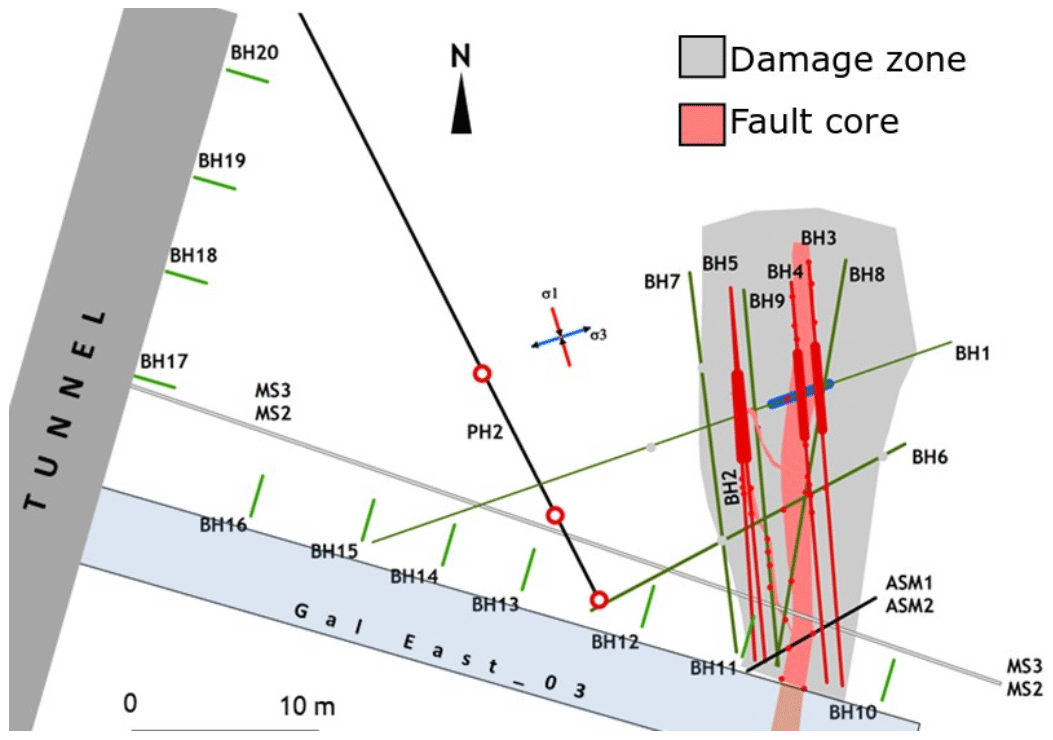
Figure 2Simplified map of the CHENILLE borehole layout. The geometry of the fault zones was determined from borehole logging and geological mapping from the galleries' floor, walls, and roof. The three main components of the fault zones are represented in this sketch: the fault core (red), the damage zone (grey), and the undisturbed protolith (white).
The target area is located at the level of the F2 fault 10 m from the northern wall of the Gallery East_03. The borehole layout of the test (Fig. 2) consists of (i) one (BH1) 30 m long injection borehole (borehole core diameter: 96–63 mm) located in the Gallery East_03 following a N72∘ direction parallel to the minimum stress value (σ3) and crossing the entire F2 fault zone, (ii) four (BH2 to BH5) 18 m long heating boreholes (borehole-core diameter: 96–63 mm) located either side and parallel to the fault core following an approximate N-S direction. Each heating borehole will be equipped with a 4 m long heater that will be cemented in the borehole. The heaters will generate temperatures exceeding 200 ∘C and enable the BH1 injection zone to reach temperatures of about 150 ∘C. In addition, a high-temperature fibre-optic cable will be installed along the heating boreholes to monitor the temperature distribution along the borehole axis with high spatial resolution. Finally, (iii) four seismic monitoring boreholes (BH6 to BH9) – each 17 m long and with a diameter between 76–48 mm – will be equipped with AE sensors to monitor small-scale seismic deformation.
Before being equipped, detailed petrophysical studies as well as µCT analyses of selected cores from the boreholes will be performed. Results will be integrated in a 3D geological model, and will provide valuable input data for future numerical studies.
3.3 Hydraulic stimulation and test procedure

The injection borehole (BH1) is about to be equipped with chamber delimited by two temperature resistant packers (Fig. 3). The upper part of the borehole (between the chamber and the borehole mouth) will be cemented and equipped with an injection tube and fiber optics for distributed temperature measurements (see Sect. 3.4). The chamber is designed to perform pressure tests during the heating phase.
3.4 Thermal stimulation instrumentation and temperature monitoring
The heating boreholes will each house a 4 m long stainless-steel heating canister. The heaters will contain spiral resistors enabling a heating power of 4000 W at 230 V. The heating canisters were designed to generate, incrementally, temperatures in the order of 150 ∘C in and around the vicinity of the injection interval.
The temperature evolution along the four heating boreholes will be monitored using distributed temperature sensing (DTS). This is probably the most frequently applied fibre-optic sensing method, which has also been used with increasing success for geophysical applications in boreholes during the past 30 years (Henninges and Masoudi, 2020).
Using DTS technology, an optical fiber acts as the sensing element. As there are no electronic parts required, fiber-optic sensors have some advantages over conventional sensors, including ruggedness, flexibility and ease of deployment, high temperature tolerance, and immunity to electromagnetic interference. With a proper DTS installation and system, a measurement accuracy of ±0.3 ∘C can be achieved (e.g. Henninges et al., 2005a). The resolution or repeatability of the measurement depends on a number of factors including the length of the fiber, and the integration time over which the data is averaged. As an example, for a fiber length of 1000 m and 10 min integration time, an RMS error of 0.02 ∘C has been reported (Voigt et al., 2011). For the DTS monitoring at Tournemire, an interrogator from Sensa is planned to be used, which enables measurements with a spatial resolution of 1 m and a sampling space which can be selected between 0.25 and 1 m.
Under harsh environmental conditions such as high temperature and excessive pressure, the fiber attenuation can be altered through a process known as hydrogen ingression or darkening, which can lead to a rapid degradation of the measurement data (e.g. (Smithpeter et al., 1999). The coating material protects the optical fiber against adverse chemical influences and primarily determines the temperature tolerance. Metal-coated fibers have the highest temperature tolerances, but usually also exhibit high attenuation, especially at low temperatures (Reinsch and Henninges, 2010), which limits their use to very short sensing ranges. A coating comprised of an outer high-temperature tolerant polyimide layer and an additional carbon layer, which offers some protection against hydrogen ingression, is referred to hermetic coating. During a field test in a high-temperature geothermal well in Iceland, Reinsch et al. (2013) have successfully deployed hermetic coating fibers at temperatures up to 230 ∘C over a period of 14 d, but reported different signs of degradation occurring after exposure to temperatures above 300 ∘C. As this is within the expected temperature range of 200–250 ∘C for the heating boreholes, such fibers will also be used for the current experiment.
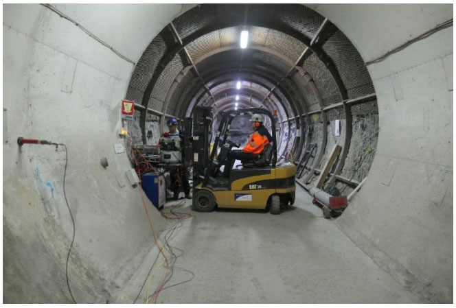
Figure 4View into the gallery east-03 from the main tunnel showing the impact seismic source mounted at a fork lifter. In the foreground the tail end of a seismic receiver is located at the left tunnel wall.
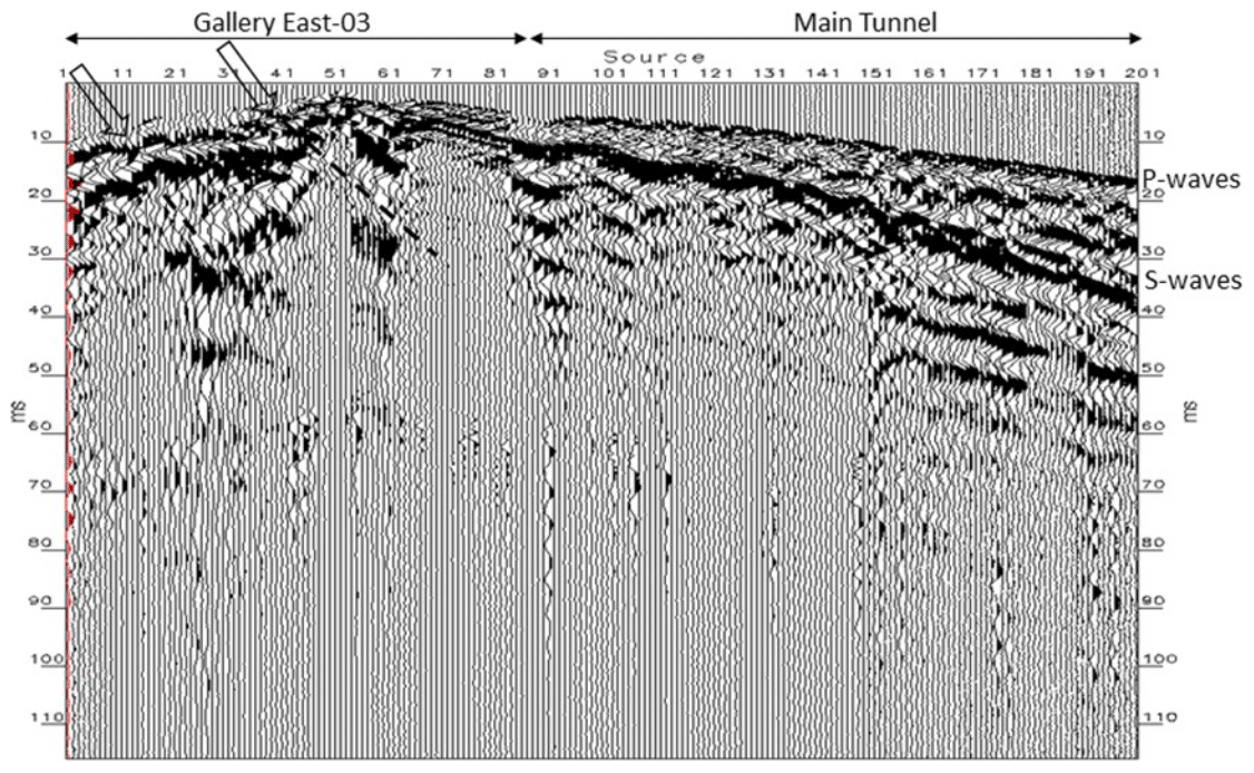
Figure 5Raw data example of seismograms recorded by the radial component in BH14. Arrows mark later P-wave arrival times which indicates the location of fault core and possible fractured zones within the damaged zone along in gallery East-03.
For deployment in boreholes, sensor cables must be designed to protect the optical fibers against mechanical stress, and to withstand the environmental conditions like temperature, pressure and corrosive fluids. For installation in the four heating boreholes, a sensor cable design with an inner stainless-steel tubing hosting the optical fibers and an outer steel wire jacket for additional mechanical strength and protection has been chosen. The fiber-optic sensor cables will be installed in a loop configuration, allowing to interrogate the optical fiber from both sides. They will be fixed to the outside of the heater elements, extending as long as possible towards the tip of the borehole, using suitable devices to protect the cables from mechanical damage during installation.
For these reasons, two kinds of arrays will be deployed: one allowing for the temperature distributed monitoring (Raman) (Henninges et al., 2005b), and one for deformation measurement (Brillouin). The first array will provide accurate information on the temperature evolution along the heating boreholes. The DTS data will allow to derive petrophysical properties such as thermal conductivity and heat capacity of the surrounding host rocks. The second array will be an essential tool to understand the influence of thermal loading on a fault zone.
3.5 Passive seismic monitoring
Monitoring seismic deformation and resulting high-frequency signals in clay rich rocks is challenging due to strong attenuation and anisotropy present in the rock mass (e.g. Plenkers et al., 2022; Kwiatek et al., 2011; Bohnhoff et al., 2009). During the Faults&Fluids (De Barros et al., 2016) project at the Tournemire URL, accelerometers sensitive in a frequency range between 2 Hz and 4 kHz were installed in boreholes within the same fault zone. These allowed for the detection of 32 events with magnitudes ranging between M−4.3 and M−3.7. Within this project, we intent to further extend the observed frequency range both to higher and lower frequencies by using the AE sensors and broadband seismometers, respectively. It is anticipated that the AE sensors that are sensitive between 1–60 kHz will be capable to detect seismic events of sub-dm size (see earlier successful monitoring campaigns in crystalline and metamorphic rocks, e.g., Boese et al., 2022; Kwiatek et al., 2011, 2018) with magnitudes down to M−6.0. The key element of success is to overcome the attenuation by installation of AE sensors close to the expected seismic sources and ensure good coupling of the sensors. We will install 12 AE sensors in the boreholes at distances up to 5 m from the stimulated intervals to limit the effect of strong attenuation expected in shales (see also part dedicated to active seismic monitoring). Previously, events with were detected in crystalline environment (Plenkers et al., 2011) at comparable distances. The AE sensors will be installed as perpendicular to the borehole trace and anchoredagainst the borehole wall to optimize the coupling quality. The intended network layout, shown in Fig. 2, was optimized for the 3D coverage of the injection interval, enabling more accurate location of seismic events and estimation of focal mechanisms (cf. Boese et al., 2022; Kwiatek et al., 2018). The acquisition system will work in continuous mode at 200 kHz sampling rate allowing to record full waveforms. In parallel, triggering-mode recordings will be performed during stimulation campaigns to optimize the recording conditions. The passive measurements will be accompanied with active ultrasonic transmission measurements. The ultrasonic transmitter will be pulled along the injection borehole generating high-frequency impulsive signals that will be recorded with AE sensors. This allows to (i) measure the P-wave velocity and its 3D anisotropy in the direct proximity of stimulation site (e.g. Boese et al., 2022), (ii) assess the attenuation through analysis of frequency-dependent amplitude decay, (iii) test and further improve the coupling of AE sensors to the borehole walls. In addition, also active measurements using sledge-hammer and centre-punch tools (Boese et al., 2022) will be used along the tunnel walls to test the wave transmissivity through the rock medium.
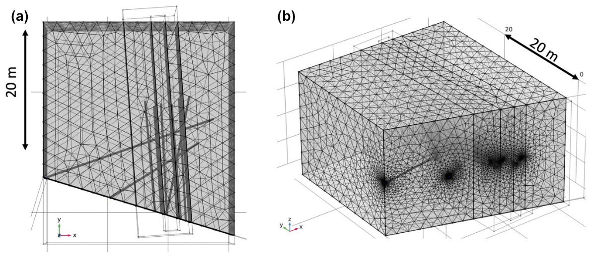
Figure 6(a) bird-view and (b) side-view of the 3D domain used for the numerical simulation the thermal stimulation. Borehole and tunnel gallery East 03 locations correspond to their exact place as shown in Fig. 2.
Attempts to monitor slow deformation processes using broadband seismic sensors and tilt sensors have been performed beforehand in hydraulic fracturing experiments performed in volcanic and metamorphic rocks. The tilt of sensors was observed at Äspö/Sweden (Zang et al., 2017) and at Grimsel Test Site/Switzerland (Gischig et al., 2018). Within the STIMTEC/Germany project (Boese et al., 2022), low-frequency signals responding to injection pressure have been observed during some hydraulic fracturing or refracturing stages. The interpretation of such recorded signals is still challenging due to their overall scarcity and ambiguity of interpretation. Within the CHENILLE project, the six-component broadband sensor ASIR A-SiA-ULN-G4.5-GS-70 will be installed in four boreholes located very close to injection intervals. The sensor consists of a 3-component 4.5 Hz geophone and a 3-component ultra-low-noise optical accelerometer covering the range from 0.01 to 100 Hz. For time synchronization purposes, one component will be concurrently recorded using AE acquisition system operating at higher sampling rates.
3.6 Active seismic monitoring
Controlled seismic experiments using different types of impact sources (Richter et al., 2018) will be conducted to image the velocity field and the fault network in and around the rock formation targeted by the CHENILLE project. The results from the active seismic survey will complement the surface-based geological mapping and analysis of the drill cores and will be intergrated towards a background geological model as baseline for time-lapse investigations planned later on. A baseline seismic survey along the main tunnel and gallery east-03 was performed in June 2021 to explore the structures and to map the seismic rock conditions before the hydraulic stimulation experiment is taken place (see Fig. 2, short boreholes along the galleries). The survey length is about 100 m with a source point interval of 0.5 m. Two different pneumatically driven impact sources (Fig. 4) were used in a comparative test in 1 m interval each.To prove the repeatability of the sources and to increase the signal-noise ratio by vertical stacking three and five shots were fired per source point. In total, 821 shots were recorded by 15 three-component geophone receivers (28 Hz) of about 6 to 7 m interval installed in 2 m deep boreholes (BH10 to BH26 in Fig. 2). The selection of the source type for the baseline Tournemire survey is based on a previous seismic experiment conducted in the Mont Terri URL (Esefelder et al., 2021; Wawerzinek et al., 2022).
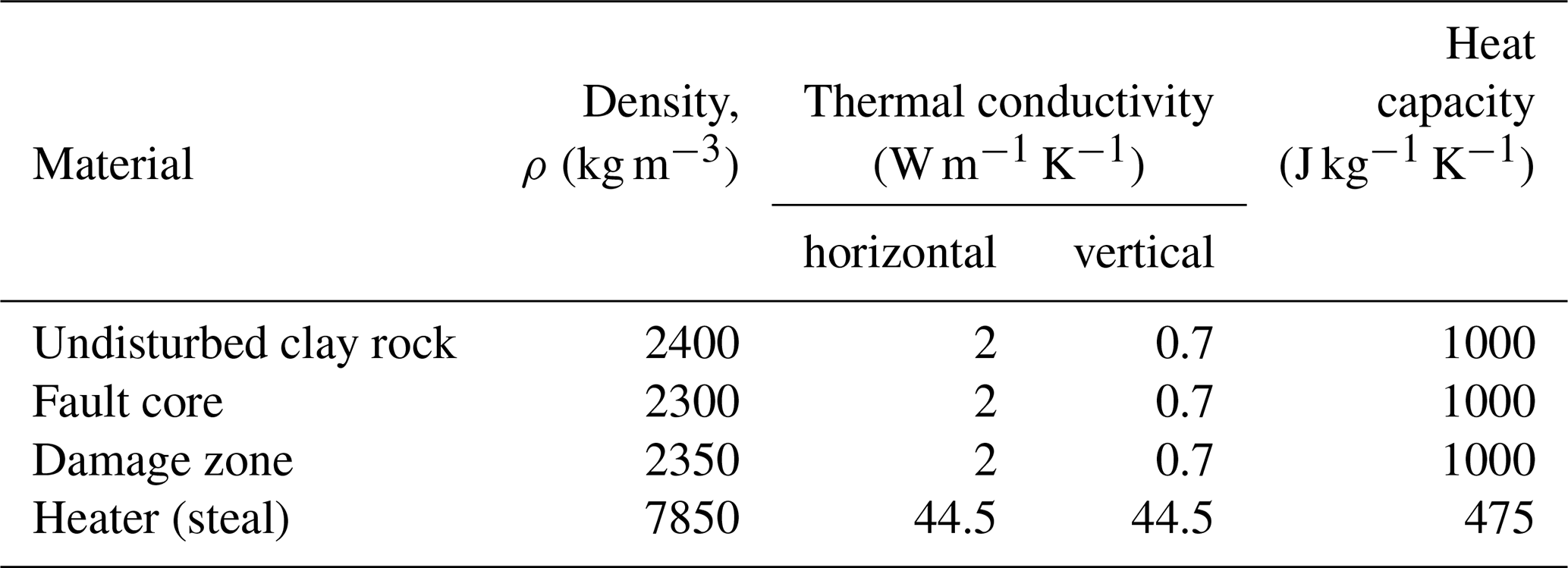
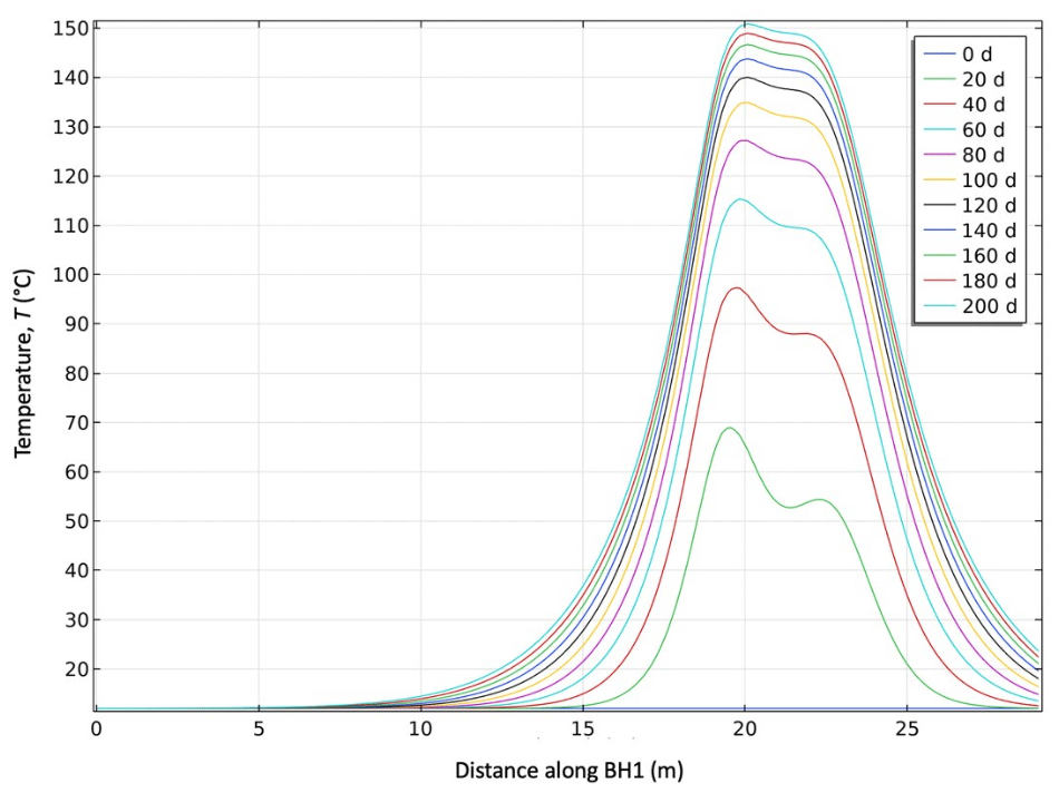
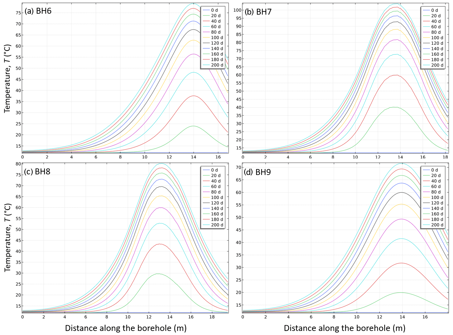
Figure 8Evolution of the temperature along the heating boreholes (BH6 to BH9, panels a to d respectively) during the thermal stimulation.
Raw data recordings are characterized by P-, S- waves and surface waves in the frequency range of 30 to 1000 Hz in an offset range of up to about 5 m. Beyond this range the maximum signal frequencies decrease quickly below 500 Hz. Figure 5 depicts a raw data example of the radial component of the receiver in borehole BH 14 (Fig. 2). The fault core zone (see Fig. 5) is characterized by delayed arrival times of the direct waves as well as back-propagated surface waves (arrows in Fig. 5). These delayed arrival times can be observed also at other locations along gallery East-03 which indicates the complexity of the fault zone.
It is intended to apply 3D-imaging techniques combining tomographic and migration inversion techniques to gain images for P- and S- waves in the area of about 50 m around the tunnel with resolution of about 0.5 m (Ciese et al., 2005; Lüth et al., 2008). Recent experiments performed with the same system in the Mont Terri URL (Switzerland) revealed a transmissivity of seismic waves for frequencies of up to 1000 Hz. The width of seismic imaging in the frame of the CHENILLE project will be completed by tomographic inversion of attenuation values (Krauß et al., 2014). The seismic attenuation is a valuable parameter to understand the rocks mechanical behaviour during hydraulic stimulation experiments.
In order to image eventual variations of the velocity field at and near the stimulation a repeat (time lapse) seismic survey will be conducted after the hydraulic stimulation of the fault core zone using the same survey layout to enable a 4D-seismic data processing. Additionally, a deeper horizontal borehole will be integrated into the survey layout applying recoverable 3C-geophone chain levels and a newly developed single-well imaging tool. In this way the resolution of the seismic imaging methods shall be increased to gain a deeper insight into fault core zone structure and possible changes due to the hydraulic stimulation.
4.1 Numerical simulations of the thermal stimulation
In order to optimize the CHENILLE stimulation experiment, we performed a numerical simulation of the heating procedure for the thermal stimulation using a finite element commercial software COMSOL Multiphysics 5.6.
For these simulations, we considered a volume of rock of 1.8×10⁴ m3 centred on the thermal stimulation set-up, hence the fault and the surrounding damaged zone. This volume contains boreholes BH1 to 9 and one of its boundaries corresponds to the wall of tunnel gallery East_03. The geometry has been chosen to be as representative as possible of the real system within the uncertainties of fault zone complex geometries describe in the previous sections. The entire active volume is constituted of clay rock except for the fault zone and the drilled boreholes. The fault core is modelled as a vertical parallelepiped of 2.23 m surrounded by two damage zones of 4.26 and 2.00 m at the left and right, respectively. The boreholes BH1 to 9 are modelled by 0.048 m radius cylinders filled by air, except for BH2 to 5 which contain a heater modelled as a 0.048 m radius and 4 m long cylinder made of steal. This domain is then meshed into more than 5.6×10⁵ tetrahedral elements as shown in Figs. 4 and 6.
The thermal stimulation is then simulated as a time-dependent thermal diffusion process as described by the following heat transfer equation:
where ρ (kg m−3) is the density, Cp (J kg−1 K−1) is the heat capacity, T (K) is the temperature, t (s) is the time, λ (W m−1 K−1) is the thermal conductivity, and Q is a heat source (W m−3). In the simulation, the boundary conditions are known and correspond to the main driver of the thermal diffusion process. The initial temperature in the entire domain is set at 12 ∘C (i.e., 285.15 K) and the heaters are turned on at t=0 s at 300 °C (i.e., 573.15 K) and kept at this temperature during the entire simulation. The domain boundaries that correspond to an interface with air, i.e., the main tunnel, the gallery East_03 and the open boreholes, are modelled with the convective heat flux boundary conditions proposed by COMSOL Multiphysics. The other domain boundaries correspond to a contact with the rest of the clay rock formation and, given the size of the domain and the duration of the simulation, the boundary condition is set to a constant temperature of 12 ∘C. The heat transfer problem is solved using the time-dependent built-in smoothed aggregation AMG solver from 0 to 200 d. Relevant physical properties of the different materials are presented in Table 2. Note that given the important anisotropy of the clay rock properties, we define their thermal conductivity as transverse isotropic.
Figures 7 and 8 present the result of the numerical simulations during the thermal stimulation. These results clearly show that the four heaters set-up will allow the thermal stimulation of the fault core and damage zone up to 150 ∘C. Figure 7 show the evolution of the temperature along the borehole BH1, while Fig. 8 shows the temperature evolution along BH6 to 9, that is outside of the focus area. Finally, Fig. 9 presents a 2D color map of the temperature at day 200 on a section that crosses the middle of the four heaters and BH1.
4.2 Expected outcomes
In-situ experiments have proven to be important tools for testing monitoring devices under real conditions, but also for a better apprehension of all the key parameters that need to be accounted for in the frame of nuclear waste disposal such as evolution of hydraulic properties, mechanical behaviour and geochemical reactions under realistic conditions. The CHENILLE project aims at participating at the efforts that were developed by the community over the past decades towards the understanding of clay rich material with investigating the influence of relatively high temperatures (up to 150 ∘C) on the mechanical behaviour of a complex zone.
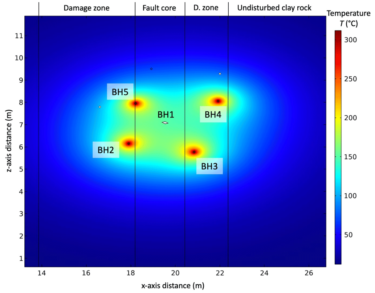
Figure 9Temperature map on a plan in the x-z direction, zoom on the stimulated area. This section crosses the middle of the heaters of BH2 to 5 and BH1 (i.e., the blank spot) as indicated on the figure. The vertical black lines indicate the location of the damage zones surrounding the fault core as written at the top of the figure.
The outcome of the CHENILLE experiment is expected to have key implications and a broad range of applications: the safety in geo-engineering (nuclear waste storage, energy storage, geothermal energy), but also for fundamental understanding of coupled THM behaviour of fault zones. The monitoring protocol developed uses state-of-the-art technologies that will be tested in clay rocks for the very first time under challenging (temperature) conditions as proposed here. By combining the results obtained in the frame of this study and experimental techniques allowing for precise description of deformation mechanisms from micro scale to centimetre scale, with the systematic use of acoustic data at all scales (and its integration) will ensure the generation and comprehension of a unique dataset.
The code is provided in open access through the a Zenodo repository and can be found at: https://doi.org/10.5281/zenodo.7693137 (Jougnot and Bonnelye, 2023).
Not applicable in our case as the paper just presents the combination of different techniques, no data is shown.
AB and PD are the PIs of the project and wrote the manuscript. RG and SL provided the set up for the active seismic part, JH provided the set up for fiber optic part, GK provided the set up for the passive seismic part, DJ made the numerical simulation. All the authors reviewed the final manuscript.
The contact author has declared that none of the authors has any competing interests.
Publisher’s note: Copernicus Publications remains neutral with regard to jurisdictional claims in published maps and institutional affiliations.
This article is part of the special issue “European Geosciences Union General Assembly 2022, EGU Division Energy, Resources & Environment (ERE)”. It is a result of the EGU General Assembly 2022, Vienna, Austria, 23–27 May 2022.
We would like to acknowledge Jonathan Dreux and Bruno Combes for their patience and enthusiasm during the drilling operations. We thank Amberg Technologies for funding the development of the new seismic impact source and Helmholtz Innovation Lab “3D-Underground Seismic” for technical and financial support for the active seismic experiment. This document is a deliverable of the European Joint Programme on Radioactive Waste Management (EURAD). EURAD has received funding from the European Union's Horizon 2020 research and innovation programme under grant agreement No 847593.
This research has been supported by the Horizon 2020 (EURAD (grant no. 847593)).
The article processing charges for this open-access publication were covered by the Helmholtz Centre Potsdam – GFZ German Research Centre for Geosciences.
This paper was edited by Christopher Juhlin and reviewed by Roberto Emanuele Rizzo, Sarah Weihmann, and one anonymous referee.
Amann, F., Gischig, V., Evans, K., Doetsch, J., Jalali, R., Valley, B., Krietsch, H., Dutler, N., Villiger, L., Brixel, B., Klepikova, M., Kittilä, A., Madonna, C., Wiemer, S., Saar, M. O., Loew, S., Driesner, T., Maurer, H., and Giardini, D.: The seismo-hydromechanical behavior during deep geothermal reservoir stimulations: open questions tackled in a decameter-scale in situ stimulation experiment, Solid Earth, 9, 115–137, https://doi.org/10.5194/se-9-115-2018, 2018.
Armand, G., Bumbieler, F., Conil, N., de la Vaissière, R., Bosgiraud, J.-M., and Vu, M.-N.: Main outcomes from in situ thermo-hydro-mechanical experiments programme to demonstrate feasibility of radioactive high-level waste disposal in the Callovo-Oxfordian claystone, J. Rock Mech. Geotech. Eng., 9, 415–427, https://doi.org/10.1016/j.jrmge.2017.03.004, 2017.
Baisch, S.: Probing the Crust to 9-km Depth: Fluid-Injection Experiments and Induced Seismicity at the KTB Superdeep Drilling Hole, Germany, B. Seismo. Soc. Am., 92, 2369–2380, https://doi.org/10.1785/0120010236, 2002.
Ben-Zion, Y. and Sammis, C. G.: Characterization of Fault Zones, Pure, https://doi.org/10.1007/PL00012554, 2003.
Bernier, F. and Neerdael, B.: Overview of in-situ thermomechanical experiments in clay: Concept, results and interpretation, Eng. Geol., 41, 51–64, 1996.
Boese, C. M., Kwiatek, G., Fischer, T., Plenkers, K., Starke, J., Blümle, F., Janssen, C., and Dresen, G.: Seismic monitoring of the STIMTEC hydraulic stimulation experiment in anisotropic metamorphic gneiss, Solid Earth, 13, 323–346, https://doi.org/10.5194/se-13-323-2022, 2022.
Bohnhoff, M., Dresen, G., Ellsworth, W. L., and Ito, H.: Passive Seismic Monitoring of Natural and Induced Earthquakes: Case Studies, Future Directions and Socio-Economic Relevance, in: New Frontiers in Integrated Solid Earth Sciences, edited by: Cloetingh, S. and Negendank, J., Springer Netherlands, Dordrecht, 261–285, https://doi.org/10.1007/978-90-481-2737-5_7, 2009.
Boisson, J.-Y., Bertrand, L., Heitz, J.-F., and Golvan, Y.: In situ and laboratory investigations of fluid flow through an argillaceous formation at different scales of space and time, Tournemire tunnel, southern France, Hydrogeol. J., 9, 108–123, https://doi.org/10.1007/s100400000119, 2001.
Bonin, B.: Deep geological disposal in argillaceous formations: studies at the Tournemire test site, Journal of Contaminant Hydrology, 35, 315–330, https://doi.org/10.1016/S0169-7722(98)00132-6, 1998.
Bonnelye, A., Schubnel, A., David, C., Henry, P., Guglielmi, Y., Gout, C., Fauchille, A.-L., and Dick, P.: Elastic wave velocity evolution of shales deformed under uppermost crustal conditions: ELASTIC ANISOTROPY OF SHALES, J. Geophys. Res.-Solid Earth, 122, 130–141, https://doi.org/10.1002/2016JB013540, 2017a.
Bonnelye, A., Schubnel, A., David, C., Henry, P., Guglielmi, Y., Gout, C., Fauchille, A.-L., and Dick, P.: Strength anisotropy of shales deformed under uppermost crustal conditions: STRENGTH ANISOTROPY OF SHALES, J. Geophys. Res.-Solid Earth, 122, 110–129, https://doi.org/10.1002/2016JB013040, 2017b.
Ciese, R., Klose, C., and Borm, G.: In situ seismic investigations of fault zones in the Leventina Gneiss Complex of the Swiss Central Alps, Geological Society, London, Special Pub., 240, 15–24, https://doi.org/10.1144/GSL.SP.2005.240.01.02, 2005.
Conil, N., Vitel, M., Plua, C., Vu, M. N., Seyedi, D., and Armand, G.: In Situ Investigation of the THM Behavior of the Callovo-Oxfordian Claystone, Rock Mech. Rock Eng., 53, 2747–2769, https://doi.org/10.1007/s00603-020-02073-8, 2020.
Davis, T. L., Landrø, M., and Wilson, M.: Geophysics and geosequestration, Cambridge University Press, 2019.
De Barros, L., Daniel, G., Guglielmi, Y., Rivet, D., Caron, H., Payre, X., Bergery, G., Henry, P., Castilla, R., Dick, P., Barbieri, E., and Gourlay, M.: Fault structure, stress, or pressure control of the seismicity in shale? Insights from a controlled experiment of fluid-induced fault reactivation: Seismicity Controlling Factors in Shale, J. Geophys. Res.-Solid Earth, 121, 4506–4522, https://doi.org/10.1002/2015JB012633, 2016.
De Bruyn, D. and Labat, S.: The second phase of ATLAS: the continuation of a running THM test in the HADES underground research facility at Mol, Eng. Geol., 64, 309–316, https://doi.org/10.1016/S0013-7952(01)00109-0, 2002.
Dick, P., Wittebroodt, C., Courbet, C., Sammaljarvi, J., Esteve, I., Matray, J.-M., Siitari-Kauppi, M., Voutilainen, M., and Dauzeres, A.: The internal architecture and permeability structures of faults in shale formations, Clay Minerals Society Workshop Lectures – Filling the Gaps – from Microscopic Pore Structures to Transport Properties in Shales , 219–229, https://doi.org/10.1346/CMS-WLS-21.17, 2016.
Esefelder, R., Wawerzinek, B., Lüth, S., Giese, R., and Krawczyk, C. M.: Seismic anisotropy of Opalinus Clay: tomographic investigations using the infrastructure of an underground rock laboratory (URL), Swiss J. Geosci., 114, 21, https://doi.org/10.1186/s00015-021-00398-2, 2021.
Faulkner, D. R., Mitchell, T. M., Rutter, E. H., and Cembrano, J.: On the structure and mechanical properties of large strike-slip faults, Geological Society, London, Special Pub., 299, 139–150, https://doi.org/10.1144/SP299.9, 2008.
Geng, Z., Bonnelye, A., Chen, M., Jin, Y., Dick, P., David, C., Fang, X., and Schubnel, A.: Elastic Anisotropy Reversal During Brittle Creep in Shale: Anisotropy Reversal During Creep, Geophys. Res. Lett., 44, 10887–10895, https://doi.org/10.1002/2017GL074555, 2017.
Gens, A., Wieczorek, K., Gaus, I., Garitte, B., Mayor, J. C., Schuster, K., Armand, G., García-Siñeriz, J. L., and Trick, T.: Performance of the Opalinus Clay under thermal loading: experimental results from Mont Terri rock laboratory (Switzerland), Swiss J. Geosci., 110, 269–286, https://doi.org/10.1007/s00015-016-0258-8, 2017.
Gischig, V. S., Doetsch, J., Maurer, H., Krietsch, H., Amann, F., Evans, K. F., Nejati, M., Jalali, M., Valley, B., Obermann, A. C., Wiemer, S., and Giardini, D.: On the link between stress field and small-scale hydraulic fracture growth in anisotropic rock derived from microseismicity, Solid Earth, 9, 39–61, https://doi.org/10.5194/se-9-39-2018, 2018.
Guglielmi, Y., Nussbaum, C., Cappa, F., De Barros, L., Rutqvist, J., and Birkholzer, J.: Field-scale fault reactivation experiments by fluid injection highlight aseismic leakage in caprock analogs: Implications for CO2 sequestration, Int. J. Greenh. Gas Con., 111, 103471, https://doi.org/10.1016/j.ijggc.2021.103471, 2021.
Hadermann, Jg. and Heer, W.: The Grimsel (Switzerland) migration experiment: integrating field experiments, laboratory investigations and modelling, J. Contam. Hydrol., 14, https://doi.org/10.1016/0169-7722(95)00035-6, 1996.
Henninges, J. and Masoudi, A.: Fiber-Optic Sensing in Geophysics, Temperature Measurements, in: Encyclopedia of Solid Earth Geophysics, edited by: Gupta, H. K., Springer International Publishing, Cham, 1–12, https://doi.org/10.1007/978-3-030-10475-7_281-1, 2020.
Henninges, J., Huenges, E., and Burkhardt, H.: In situ thermal conductivity of gas-hydrate-bearing sediments of the Mallik 5L-38 well: CONDUCTIVITY OF HYDRATE-BEARING SEDIMENT, J. Geophys. Res., 110, B11206, https://doi.org/10.1029/2005JB003734, 2005a.
Henninges, J., Zimmermann, G., Büttner, G., Schrötter, J., Erbas, K., and Huenges, E.: Wireline distributed temperature measurements and permanent installations behind casing, in: World Geothermal Congress (Antalya Turkey 2005), 2005b.
Jougnot, D. and Bonnelye, A.: COMSOL code for the numerical simulation of the thermal stimulation for the CHENILLE experiment in Tournemire (Version 1), Zenodo [code], https://doi.org/10.5281/zenodo.7693137, 2023.
Kaduri, M., Gratier, J.-P., Renard, F., Çakir, Z., and Lasserre, C.: The implications of fault zone transformation on aseismic creep: Example of the North Anatolian Fault, Turkey: Rock Transformation and Aseismic Creep, J. Geophys. Res.-Solid Earth, 122, 4208–4236, https://doi.org/10.1002/2016JB013803, 2017.
Kneafsey, T. J., Dobson, P., Blankenship, D., Morris, J., Knox, H., Schwering, P., and Valladao, C.: An overview of the EGS Collab project: field validation of coupled process modeling of fracturing and fluid flow at the Sanford Underground Research Facility, Lead, SD, in: 43rd Workshop on Geothermal Reservoir Engineering (Vol. 2018), 2018.
Krauß, F., Giese, R., Alexandrakis, C., and Buske, S.: Seismic travel-time and attenuation tomography to characterize the excavation damaged zone and the surrounding rock mass of a newly excavated ramp and chamber, Int. J. Rock Mech. Min., 70, 524–532, https://doi.org/10.1016/j.ijrmms.2014.06.010, 2014.
Kwiatek, G., Plenkers, K., Dresen, G., and JAGUARS Research Group: Source Parameters of Picoseismicity Recorded at Mponeng Deep Gold Mine, South Africa: Implications for Scaling Relations, B. Seismol. Soc. Am., 101, 2592–2608, https://doi.org/10.1785/0120110094, 2011.
Kwiatek, G., Martínez-Garzón, P., Plenkers, K., Leonhardt, M., Zang, A., von Specht, S., Dresen, G., and Bohnhoff, M.: Insights Into Complex Subdecimeter Fracturing Processes Occurring During a Water Injection Experiment at Depth in Äspö Hard Rock Laboratory, Sweden, J. Geophys. Res.-Solid Earth, 123, 6616–6635, https://doi.org/10.1029/2017JB014715, 2018.
Kwiatek, G., Saarno, T., Ader, T., Bluemle, F., Bohnhoff, M., Chendorain, M., Dresen, G., Heikkinen, P., Kukkonen, I., Leary, P., Leonhardt, M., Malin, P., Martínez-Garzón, P., Passmore, K., Passmore, P., Valenzuela, S., and Wollin, C.: Controlling fluid-induced seismicity during a 6.1-km-deep geothermal stimulation in Finland, Sci. Adv., 5, eaav7224, https://doi.org/10.1126/sciadv.aav7224, 2019.
Lefèvre, M., Guglielmi, Y., Henry, P., Dick, P., and Gout, C.: Calcite veins as an indicator of fracture dilatancy and connectivity during strike-slip faulting in Toarcian shale (Tournemire tunnel, Southern France), J. Struct. Geol., 83, 73–84, https://doi.org/10.1016/j.jsg.2016.01.002, 2016.
Lüth, S., Giese, R., Otto, P., Krüger, K., Mielitz, S., Bohlen, T., and Dickmann, T.: Seismic investigations of the Piora Basin using S-wave conversions at the tunnel face of the Piora adit (Gotthard Base Tunnel), Int. J. Rock Mech. Min., 45, 86–93, https://doi.org/10.1016/j.ijrmms.2007.03.003, 2008.
Masri, M., Sibai, M., Shao, J. F., and Mainguy, M.: Experimental investigation of the effect of temperature on the mechanical behavior of Tournemire shale, Int. J. Rock Mech. Min., 70, 185–191, https://doi.org/10.1016/j.ijrmms.2014.05.007, 2014.
Matray, J. M., Savoye, S., and Cabrera, J.: Desaturation and structure relationships around drifts excavated in the well-compacted Tournemire's argillite (Aveyron, France), Eng. Geol., 90, 1–16, 2007.
Moreno, E., Homberg, C., Schnyder, J., Person, A., David, C., du Peloux, A., Moubeche, E., Bonnelye, A., and Dick, P.: Fault imprint in clay units: Magnetic fabric, p-wave velocity, structural and mineralogical signatures, Tectonophysics, 745, 264–277, 2018.
Niandou, H., Shao, J., Henry, J., and Fourmaintraux, D.: Laboratory investigation of the mechanical behaviour of Tournemire shale, International J. Rock Mech. Min., 34, 3–16, 1997.
Peyaud, J.-B., Pagel, M., Cabrera, J., and Pitsch, H.: Mineralogical, chemical and isotopic perturbations induced in shale by fluid circulation in a fault at the Tournemire experimental site (Aveyron, France), J. Geochem. Explor., 90, 9–23, https://doi.org/10.1016/j.gexplo.2005.09.001, 2006.
Plenkers, K., Schorlemmer, D., Kwiatek, G., and JAGUARS Research Group: On the Probability of Detecting Picoseismicity, B. Seismol. Soc. Am., 101, 2579–2591, https://doi.org/10.1785/0120110017, 2011.
Plenkers, K., Manthei, G., and Kwiatek, G.: Underground In-situ Acoustic Emission in Study of Rock Stability and Earthquake Physics, in: Acoustic Emission Testing: Basics for Research – Applications in Engineering, edited by: Grosse, C. U., Ohtsu, M., Aggelis, D. G., and Shiotani, T., Springer International Publishing, Cham, 403–476, https://doi.org/10.1007/978-3-030-67936-1_16, 2022.
Reinsch, T. and Henninges, J.: Temperature-dependent characterization of optical fibres for distributed temperature sensing in hot geothermal wells, Meas. Sci. Technol., 21, 094022, https://doi.org/10.1088/0957-0233/21/9/094022, 2010.
Reinsch, T., Henninges, J., and Ásmundsson, R.: Thermal, mechanical and chemical influences on the performance of optical fibres for distributed temperature sensing in a hot geothermal well, Environ. Earth Sci., 70, 3465–3480, https://doi.org/10.1007/s12665-013-2248-8, 2013.
Richter, H., Hock, S., Mikulla, S., Krüger, K., Lüth, S., Polom, U., Dickmann, T., and Giese, R.: Comparison of pneumatic impact and magnetostrictive vibrator sources for near surface seismic imaging in geotechnical environments, J. Appl. Geophys., 159, 173–185, https://doi.org/10.1016/j.jappgeo.2018.08.010, 2018.
Romanet, P., Bhat, H. S., Jolivet, R., and Madariaga, R.: Fast and Slow Slip Events Emerge Due to Fault Geometrical Complexity, Geophys. Res. Lett., 45, 4809–4819, https://doi.org/10.1029/2018GL077579, 2018.
Schuster, V., Rybacki, E., Bonnelye, A., Herrmann, J., Schleicher, A. M., and Dresen, G.: Experimental Deformation of Opalinus Clay at Elevated Temperature and Pressure Conditions: Mechanical Properties and the Influence of Rock Fabric, Rock Mech. Rock Eng., 54, 4009–4039, https://doi.org/10.1007/s00603-021-02474-3, 2021.
Smithpeter, C., Norman, R., Krumhansl, J., Benoit, D., and Thompson, S.: Evaluation of a distributed fiber-optic temperature sensor for logging wellbore temperature at the Beowawe and Dixie Valley geothermal fields (No. SAND99-1820C), Sandia National Lab.(SNL-NM), Albuquerque, NM (United States), Sandia National Lab. (SNL-CA), Livermore, CA (United States), 1999.
Voigt, D., van Geel, J. L. W. A., and Kerkhof, O.: Spatio-temporal noise and drift in fiber optic distributed temperature sensing, Meas. Sci. Technol., 22, 085203, https://doi.org/10.1088/0957-0233/22/8/085203, 2011.
Wawerzinek, B., Lüth, S., Esefelder, R., Giese, R., and Krawczyk, C. M.: Performance of high-resolution impact and vibration sources for underground seismic exploration of clay formations at the scale of a rock laboratory, Geophys. J. Int., 231, 1750–1766, https://doi.org/10.1093/gji/ggac283, 2022.
Zang, A., Stephansson, O., Stenberg, L., Plenkers, K., Specht, S., Milkereit, C., Schill, E., Kwiatek, G., Dresen, G., Zimmermann, G., Dahm, T., and Weber, M.: Hydraulic fracture monitoring in hard rock at 410 m depth with an advanced fluid-injection protocol and extensive sensor array, Geophys. J. Int., 208, 790–813, https://doi.org/10.1093/gji/ggw430, 2017.
- Abstract
- Introduction
- Influence of temperature on hydro-mechanical behavior in clay rich rocks: a brief review of existing experiments
- Description of the in-situ experiment and monitoring
- Outlook
- Code availability
- Data availability
- Author contributions
- Competing interests
- Disclaimer
- Special issue statement
- Acknowledgements
- Financial support
- Review statement
- References