 | 24 Jul 2018
Micromechanical modeling of the Compression of the Damaged Zone experiment in the Callovo-Oxfordian formation
Joffrey Bluthé
Benoît Bary
Eric Lemarchand
A theoretical model of the Compression of the Damaged Zone experiment is proposed. The tools of micromechanics are used to represent the fractured zone. Assuming an elastic behavior of the sound COx claystone and a simplified geometry of the drift, an analytical solution is presented and the crack closure is determined as a function of distance from the drift wall for two loading cases: a prescribed 4 MPa pressure and a stress-free strain with 1 % average value to describe the swelling due to resaturation. The results are in agreement with experimental observations and give insights into the heterogeneous character of self-sealing in the damaged zone.
- Article
(332 KB) - Full-text XML
- BibTeX
- EndNote


In order to deal with high-level and intermediate-level long-lived radioactive waste (HLW and ILW-LL), the French national radioactive waste management agency (ANDRA) is planning on building an underground repository in the clay-rich Callovo-Oxfordian formation at Bure, at a depth of about 500 m (Andra, 2016b). This concept relies on the excavation of a network of drifts, which is known to lead to localized damage along said drifts, and thus to a significant increase of the hydraulic conductivity (Armand et al., 2014). ANDRA was thus led to design swelling seals for horizontal drifts oriented along the horizontal major stress, and to investigate the so-called self-sealing ability of the Callovo-Oxfordian claystone, that is the tendency of open cracks to close upon hydration of the rock.
Self-sealing has received considerable attention in recent years, mostly in the form of experimental studies performed by ANDRA and other research teams on this and similar clay rock formations (Blümling et al., 2007; Davy et al., 2007; Ghayaza et al., 2013; Zhang, 2011, 2013). However, few attempts have been made at explicitly modeling the evolution of the damaged zone upon hydration of the rock, especially in the case of the Callovo-Oxfordian (COx) claystone. Different approaches have been proposed in the literature over the years to model self-sealing in the Opalinus clay of Mont Terri: Xu et al. (2013) and then Le and Nguyen (2014) developed a coupled two-phase flow and mechanical model to simulate both the creation of the damaged zone and its subsequent sealing due to resaturation by introducing a strain dependent permeability; Lisjak et al. (2016) proposed a hybrid finite-discrete element simulation of the formation of the damaged zone and its mechanical sealing by an increase in radial pressure, whereby permeability changes directly result from the appearance of failed crack elements and invoking the so-called cubic law; Alcolea et al. (2017) formulated an abstraction of the damaged zone whereby the crack pattern is calculated during a purely mechanical computation, then used to determine the heterogeneous permeability, and finally an effective homogeneous damaged cell is proposed to match the overall hydraulic properties of the drift.
In this paper, a micromechanics-based model of the damaged zone is proposed so as to interpret results from the Compression of the Damaged Zone (CDZ) experiment performed at the Bure underground research laboratory (URL). First, this experiment is briefly described in Sect. 2 (see de La Vaissière et al., 2015 for a more detailed account), and a simplified geometry and boundary value problem are presented in Sect. 3. The homogenization step is described, with a special focus on the determination of the crack opening variation during the experiment. The problem is made linear by assuming that the cracks remain open during the experiment and that they have vanishing aspect ratios. Then, the results are presented and discussed in Sect. 4. Finally, conclusions are drawn and perspectives are presented for future works.
The goal of the CDZ experiment, performed at the main level of the Bure URL, was to investigate the effects of both the mechanical loading and rehydration of the rock on the properties of the damaged zone. The former was studied by applying a 4 MPa pressure on the drift walls through the use of a hydraulic device, and the latter by injecting water directly in the crack network. They respectively simulate the presence of a swelling clay core in the drift, and the resaturation process that will occur during the post-closure phase of the project. These experiments were performed in the Galerie d'Expérimentation Trois (GET) drift, whose average diameter is 5.44 m (Armand et al., 2014). The initial fracture network is made up of three parts (de La Vaissière et al., 2015), the first of which contains the open tensile fractures and extends up to a distance of about 1.1 m from the drift wall, i.e. 40 % of the drift radius. It has been shown (Armand et al., 2014) that this particular zone coincides with the high conductivity part of the damaged zone, which leads to believe that it is essentially the tensile fractures that are responsible for this increase. Around the GET drift, the zone with a connected crack network is roughly elliptical with its major axis in the horizontal direction and its minor axis in the vertical direction, and the semi-major and semi-minor axes are on the order of 1.8R and 1.3R respectively, where R is the drift radius (see Andra, 2016a).
The evolution of the state of the damaged zone was monitored by performing hydraulic measurements with multi-packer systems. The first phase of the experiment consisted in mechanically compressing the damaged zone. In order to prevent unwanted self-sealing prior to application of the load, the intervals were immediately filled with nitrogen at atmospheric pressure after the coring procedure, except for the end intervals which were filled with synthetic water. Thus, gas tests were performed during the loading cycle to measure its impact on the damaged zone. After the mechanical tests were performed, the drift walls were unloaded, synthetic water was injected in the gas-filled intervals up to full saturation, and displacements of the jack were blocked. This allowed for hydration of the crack network during one year and monitoring of the swelling of the COx claystone. Hydraulic tests were performed during this one-year injection phase, and for six months after injection was stopped. Note that in both gas and water tests, hydraulic conductivities are not directly measured but are instead recovered using different softwares to interpret the results (see de La Vaissière et al., 2015 for details).
The main results obtained are as follows. For the first part of the experiment, loading was able to reduce hydraulic conductivities by one to four orders of magnitude for boreholes behind the loading device, depending on the distance of the interval from the drift wall. At a distance between 2 and 3 m from the drift wall (74 and 110 % of the drift radius) the influence of the loading stops. It is also worth noting that loading did not impact significantly the conductivity outside the loading area, that is for boreholes that were not located directly behind the hydraulic device. This drop in hydraulic conductivity is associated with closure of the open tensile fractures mentioned above, without saturation of the crack network. After unloading of the drift walls, the hydraulic conductivities remained below their initial values. For the second part of the experiment, further decrease of the hydraulic conductivities up to two to four orders of magnitude was observed over the first few days of hydration, especially for intervals with initial conductivities above .
3.1 Geometry, constitutive relations and boundary value problems
In this section, a simplified representation of the structure, its behavior and the boundary conditions is proposed. First, the geometry is described. The drift is assumed to be circular with radius R, and the damaged zone is also assumed to be circular, with external radius 1.53R so as to ensure that the cross-sectional area of the damaged zone is correct, as suggested in Andra (2016a) (). Additionally, the cracks are assumed to be open tensile cracks parallel to the drift walls, since the shear fractures do not seem to affect the hydraulic conductivity so much as previously noted. They are modeled as a set of flat spheroids with semi-major axis a and semi-minor axis c, and their minor axes are assumed to be parallel to the vector er of the local polar basis. When solving the boundary value problems, these cracks will not be represented explicitly, but rather a homogenization scheme is used to replace the damaged zone with an effective micro-cracked medium. Finally, plane strain conditions are assumed in the cross section of the drift, i.e. in the xy-plane (see Fig. 1).

A linear elastic isotropic relation is assumed for the undamaged claystone, with stiffness tensor , where 𝕁 and 𝕂 are the spherical and deviatoric fourth-order projectors. These projectors are such that , where 𝕀 is the fourth-order symmetric identity tensor. Since the damaged zone is assumed to be made of micro-cracks embedded in the undamaged claystone, the same relation is assumed at the microscopic scale. However, the assumption made on the orientation of the cracks yields a transversely isotropic stiffness tensor around the er axis at the macroscopic scale (see Sect. 3.2). Additionally, the prestress generated by the overburden is disregarded since it only affects the sealing process through viscous phenomena which are not modeled here.
Two loading cases are proposed to comply with the CDZ experiment: on the one hand a uniform pressure p=4 MPa is prescribed at the drift walls, and on the other hand an isotropic stress-free strain is prescribed in the damaged zone together with zero surface tractions at the drift wall. In both cases, the displacements are assumed to vanish at infinity (see Fig. 2). These two problems will be referred to as problem (i) and problem (ii) respectively. For problem (ii), the stress-free strains, introduced to model swelling phenomena in the damaged zone, are assumed to be isotropic although it has been shown experimentally that they are quite anisotropic because of the presence of a bedding plane (see for example Zhang et al., 2010 and Wang et al., 2013). Also, note that the magnitude of the swelling is assumed to be only a function of the distance from the drift wall, which is more likely to be realistic during progressive resaturation of the claystone in the post-closure phase than in an injection experiment. However, these assumptions endow the problem with rotational symmetry about the drift axis which allows for an analytical treatment. Finally, zero surface tractions are applied at the drift wall instead of zero displacements as in the actual experiment because here the whole annulus region is subjected to swelling which leads to divergence of the wall. Thus, blocking the displacements would lead to unrealistic radial tensions at the drift wall.
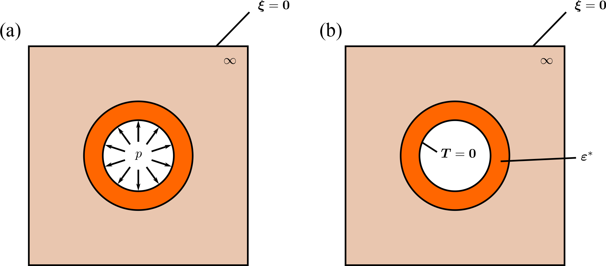
Figure 2(a) Illustration of the boundary conditions of problem (i). (b) Illustration of the boundary conditions of problem (ii).
The constitutive relation of the undamaged claystone subjected to the stress-free strain ε* reads:
where σ is the Cauchy stress tensor, ε is the total linearized strain and “:” is the usual double contraction on tensors. It will be shown in Sect. 3.2 that the homogenized behavior of the damaged zone is identical but with a different stiffness tensor ℂdam. Let x denote the radius vector, ξ the total displacement and ∇ the gradient operator, the boundary value problems may be stated as follows:
with for problem (i) and p=0 for problem (ii).
3.2 Homogenized behavior in the damaged zone
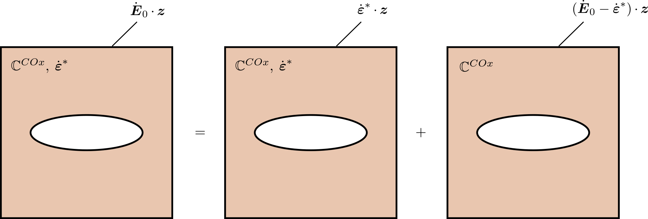
In the following, a separation of scales is assumed between the drift of characteristic size R, and the cracks of characteristic sizes a. This ensures the possibility of introducing a representative elementary volume (REV) made up of spheroidal parallel open cracks embedded in an otherwise undisturbed clay matrix with stiffness tensor ℂCOx. Since cracks usually have very small openings, small strains of the rock mass can lead to finite strains of the crack domain (e.g. complete closure). Thus, following Deudé et al. (2002), the mechanical behavior of the REV is investigated in its rate form, which allows for the tools of linear homogenization to be used. The REV is subjected to both the macroscopic strain rate , and a local stress-free strain rate . Following the Mori-Tanaka scheme, an auxiliary problem is introduced, whereby a single crack is embedded in an infinite matrix with uniform strain rate boundary conditions at infinity, where z is the radius vector at the microscopic scale, and an auxiliary strain rate to be defined. Using the principle of superposition, the auxiliary problem is described as the superposition of two sub-problems with uniform strain rate boundary conditions (see Fig. 3): in the first sub-problem, the stress-free strain rate is applied both in the matrix and at the boundary of the REV, while in the second problem, no stress-free strain rate is applied in the matrix, but is applied at the boundary of the REV. The solution to these problems is readily obtained:
The tangent stiffness tensor ℂ(z) is equal to 0 in the cracks and ℂCOx in the matrix, and 𝔸(z) is the fourth-order localization tensor. Note that all the fields are extended to the crack domain in Eshelby's classical problem, by replacing the crack with a material with stiffness tensor ℂCOx and by adding a so-called polarization so that in the crack . Since the crack is assumed to be a spheroid, Eshelby's classical result (Eshelby, 1957) states that is uniform in the crack for the second problem, and its value for the superposition of the two problems is thus derived:
with , where is Eshelby's tensor for a crack in the COx matrix. Here, the dependence of Eshelby's tensor on the current stress through the aspect ratio of the crack is highlighted. This makes the macroscopic behavior of the damaged zone nonlinear and justifies the rate formulation used here. Using the strain rate average rule , where f is the volume fraction of the crack domain, and the assumptions that and , is obtained as a function of . Then, substitution in Eq. (4) yields:
The macroscopic stress rate also easily follows from the stress rate average rule , which reduces to and yields:
where the Mori-Tanaka estimate for the homogenized stiffness tensor
has been introduced. The macroscopic stress rate-strain rate law is of the same type as the microscopic one, with the same stress-free strain rate . In order to finish the homogenization procedure, the limit as the aspect ratios of the cracks approach 0 will be taken. Following Deudé et al. (2002), first note that , where 𝒩 is the number of cracks per unit volume and ϵ=𝒩a3 is the crack density parameter (Budiansky and O'connell, 1976). Then, it can be shown (Horii and Nemat-Nasser, 1983) that X𝔸c has a finite limit 𝕋 as X→0 which only depends on the orientation of the crack family and the Poisson's ratio of the solid phase, so that the homogenized stiffness reads:
The Voigt representation of 𝕋 is recalled in Appendix A. Note that in the limit X≪1, the homogenized stiffness ℂdam does not depend on X, and thus on Σ anymore, so that the problem becomes linear, as long as the cracks remain open. Under this assumption, the rate of change of the semi-minor axis of the cracks can be estimated by , with n the unit vector in the direction of the minor axes of the cracks, which, as X→0 reads:
Using Eqs. (6) and (7), the following expression is obtained in terms of the macroscopic stress tensor:
This equation can be integrated with respect to time to yield:
for an evolution of the macroscopic stress from 0 to Σ without complete closure of the cracks. In the same way, the constitutive relation Eq. (7) can be integrated with respect to time:
Note that the more general case of a distribution of aspect ratios is straightforward (see Deudé et al., 2002).
3.3 Solution of the boundary value problems
As was shown, as long as all the cracks remain open the tangent stiffness of the damaged zone is constant, so that the problem is actually linear. In that case, the problem has a simple solution due to its rotational symmetry. The solution is first proposed in the damaged zone, which is considered to be transversely isotropic and subjected to the stress-free strain , and the solution in the undamaged zone follows immediately. The total displacement is looked for in the form ξ=f(r)er and is introduced in the equation of equilibrium. It is convenient to notice that the stiffness tensor of the damaged zone ℂdam(θ) which is a function of θ (see Fig. 1), is most easily expressed in the cylindrical basis (see Appendix A). Using the compatibility equation Eq. 2 and the constitutive relation Eq. (2), the equation of equilibrium yields the following second order ordinary differential equation for the function f:
The coefficients α, β and γ read (see Appendix A):
Note that in the isotropic case α=1 and γ=0. Let fhom be the solution of the associated homogeneous differential equation. It has the form:
where A and B are two constants of integration to be determined with boundary conditions. A particular solution to the complete differential equation is also found when g(r) has the special form g(r)=gprp. In that case, a particular solution reads:
Since the differential equation is linear, a solution immediately follows for every polynomial function of r. Also, since any continuous function of r on the closed interval [R,1.53R] can be approximated as closely as desired by a polynomial function, an approximate solution can be found for such functions.
4.1 Parameters
The parameters used for the numerical results are presented in Table 1. Note that the elastic constants of the undamaged claystone were averaged using the values measured in Pham (2006) prior to and after resaturation of the sample. Also, the 1 % value given for the stress-free strain is actually its average on the damaged zone. Much higher strains were obtained during free-swelling experiments (up to 12 % volumetric strains, Zhang et al., 2010), but much lower strains were obtained under high triaxial stresses (volumetric strains on the order of 0.1 %, Zhang et al., 2010), so a conservative average value of 1 % was considered since the rock is likely to be in a relatively confined state in situ. Finally, to simplify and due to the lack of experimental data, only one family of cracks is considered in this first attempt, and the crack density parameter ϵ is set to 10−3. It is worth noting that in the range 10−1–10−6, this parameter has only a minor influence on the crack closure, so that the value could be chosen arbitrarily.
Pham (2006)Pham (2006)Zhang et al. (2010)Andra (2016a)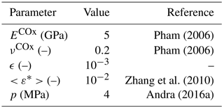
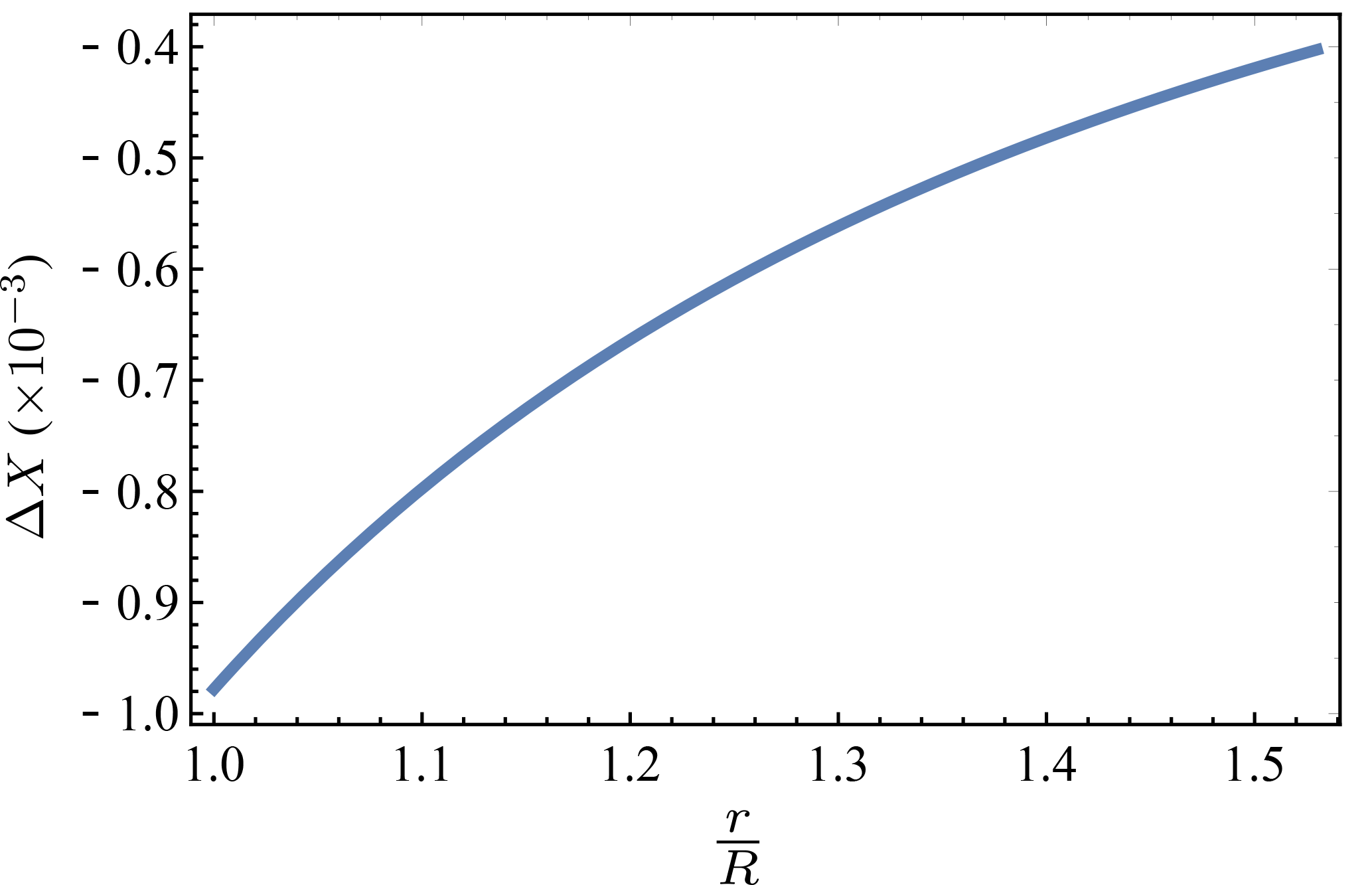
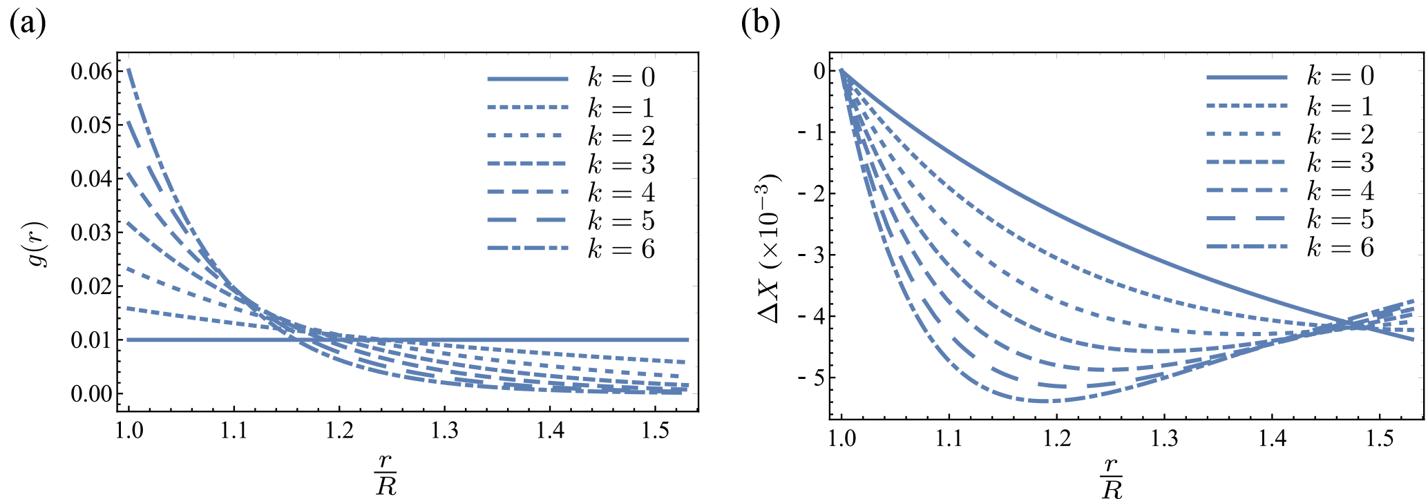
Figure 5(a) Stress-free strain and (b) crack closure for problem (ii) for different values of k.
4.2 Prescribed pressure
Figure 4 shows the evolution of the aspect ratio of the cracks with the distance from the drift wall. It is most easily obtained from Eq. (11) by dividing by the crack semi-major axis. The decreasing influence of the applied pressure as the distance from the drift wall increases as observed in de La Vaissière et al. (2015) is recovered. Still, it is hard to compare the zones of influence because in the proposed model the damaged zone stops at a distance of 0.53R, while in the experiment the influence of the loading stops between distances of 0.74R and 1.1R. This is due to the fact that the actual damaged zone for this kind of drift has a larger horizontal extension.
4.3 Stress-free strain
Figure 5 shows (a) an exponentially decaying prescribed stress-free strain with average value 1 % and (b) the resulting crack closure. This type of variation for g(r) is based on the fact that the claystone resaturation is likely to be a decreasing function of the distance from the drift wall, and thus so is its swelling potential. The function g(r) is then proposed in the form:
with k a dimensionless parameter that makes the stress-free strain decay more or less rapidly, and thus also the maximum swelling more or less important. Only values of k lower than 6 were chosen to yield a reasonable maximum swelling strain (see Sect. 4.1).
Two facts are worth noting about the resulting curves. First of all, the maximum magnitude of the crack closure is about five times greater than in the prescribed pressure case. This means that such a swelling has a far greater crack closing potential than pure mechanical loading. This conclusion is consistent with observations made by Davy et al. (2007) who noted that purely mechanical loading was able to reduce gas permeability by a factor of up to 42, while water injection was able to reduce water permeability by a factor as high as 3000. Secondly, the monotony of ΔX(r) is completely different in the case of a prescribed stress-free strain: it is either a decreasing function of r, or a decreasing and then increasing function of r, depending on the value of k. It is interesting to observe that the local magnitude of closure is not correlated with the local magnitude of the prescribed swelling, since the swelling is highest at r=R where closure is at its lowest. Also, note that all the curves present similar values for the highest closure, which suggest that it is related to the average value of the swelling more than to the actual shape of the curve.
4.4 Discussion
The crack closures discussed so far were expressed in terms of aspect ratio. In order to derive the actual change in crack opening Δc, the crack width a is needed. This is a quite complicated parameter to evaluate in situ, however one can draw comparisons with other existing models. For example, Hawkins et al. (2011) proposed to model the “small random fractures”, which are suspected of being critical for the hydraulic conductivity of the structure, with a set of squares with sides equal to 0.5 m and roughly parallel to the drift wall. This value relies on the experimental results of Proudhon (2008). Although it was not specifically said in Hawkins et al. (2011), the damage state described there seems to be that found around a drift parallel to the horizontal minor stress, which is quite different from the one studied here. For lack of more precise data, the value a=0.25 m will be considered here. Additionally, initial apertures are expected to be on the order of the millimeter (Proudhon, 2008). Thus, values of above are expected to lead to complete closure of the cracks. This value is well within the range of crack closures computed here for the swelling experiment, and are at least of the same order of magnitude as those computed for the compression experiment, which is encouraging for the soundness of the proposed model.
Finally, it is worth noting that a particular feature of this model is that self-sealing appears to be heterogeneous in the damaged zone, and the zones where it is efficient depend on the loading. As a consequence of the assumption of invariance with respect to z, if self-sealing does not occur in the whole damaged zone the structure as a whole could still posses a high hydraulic conductivity. However, the crack network is really made up of macroscopic oblique cracks that are connected, and thus local self-sealing at a certain location in the damaged zone could in principle cut the potential pathway and lead to a significant reduction in overall hydraulic conductivity of the structure. Thus, this model is a quite pessimistic representation of the self-sealing phenomenon.
A simplified model of the Compression of the Damaged Zone was proposed to investigate the self-sealing properties of claystone at the scale of the drift from a theoretical point of view. The results obtained are as follows: (1) a 1 % average swelling strain in the damaged zone leads to far better self-sealing than a 4 MPa prescribed pressure at the drift wall, and (2) self-sealing appears to be highly heterogeneous as a function of the distance from the drift wall and depends on the distribution of the resaturation-controlled stress-free strain, but its magnitude seems to be influenced essentially by the average strain. This simplified analytical approach could be validated by comparing the results with numerical simulations in a more realistic setting taking into account a more realistic geometry of the drift and of the crack network as well as viscoplasticity of the claystone.
Further developments will follow this preliminary study. Because of the dependence of the results on the distribution of the stress-free strain, a more realistic distribution needs to be computed from a coupled hydromechanical model taking into account water transport phenomena. Also, several crack families may be considered to see how they might interact with each other in the context of completely closing cracks, which makes the problem non-linear. Different orientations for the cracks may be investigated, since the actual cracks are not strictly parallel to the drift walls. In addition, stronger crack interactions might be studied by considering a self-consistent scheme rather than a Mori-Tanaka scheme.
In the basis , where e3 is the vector normal to the mid-plane of the cracks, the tensor 𝕋 has the following Voigt representation:
The only two components of interest for us are T3311 and T3333 and are recalled in Deudé (2002):
where νs is the Poisson's ratio of the solid phase.
The stiffness tensor ℂdam(θ) of a transverse isotropic material with er as direction of transverse isotropy has the following Voigt representation in the cylindrical basis :
where c1111, c3333, c1122, c1133 and c2323 are five independent material coefficients that do not depend on θ.
No data sets were used in this article.
JB proposed and developed the model, performed all the computations and wrote the manuscript. BB and EL supervised this work, discussed the results and provided critical feedback on the manuscript.
The authors declare that they have no conflict of interest.
This article is part of the special issue “European Geosciences Union General Assembly 2018, EGU Division Energy, Resources & Environment (ERE)”. It is a result of the EGU General Assembly 2018, Vienna, Austria, 8–13 April 2018.
EDF is gratefully acknowledged for financially supporting this
research.
Edited by: Michael
Kühn
Reviewed by: two anonymous referees
Alcolea, A., Kuhlmann, U., Marschall, P., Lisjak, A., Grasselli, G., Mahabadi, O., de La Vaissière, R., Leung, H., and Shao, H.: A pragmatic approach to abstract the excavation damaged zone around tunnels of a geological radioactive waste repository: application to the HG-A experiment in Mont Terri, Geological Society, London, Special Publications, 443, 127–147, 2017. a
Andra: Dossier d'options de sûreté – Partie après fermeture (DOS-AF), 2016a. a, b, c
Andra: Dossier d'options de sûreté – Partie exploitation (DOS-EXPL), 2016b. a
Armand, G., Leveau, F., Nussbaum, C., de La Vaissiere, R., Noiret, A., Jaeggi, D., Landrein, P., and Righini, C.: Geometry and properties of the excavation-induced fractures at the Meuse/Haute-Marne URL drifts, Rock Mech. Rock Eng., 47, 21–41, 2014. a, b, c
Blümling, P., Bernier, F., Lebon, P., and Martin, C. D.: The excavation damaged zone in clay formations time-dependent behaviour and influence on performance assessment, Phys. Chem. Earth, Parts A/B/C, 32, 588–599, 2007. a
Budiansky, B. and O'connell, R. J.: Elastic moduli of a cracked solid, Int. J. Solid. Struct., 12, 81–97, 1976. a
Davy, C. A., Skoczylas, F., Barnichon, J.-D., and Lebon, P.: Permeability of macro-cracked argillite under confinement: gas and water testing, Phys. Chem. Earth, Parts A/B/C, 32, 667–680, 2007. a, b
de La Vaissière, R., Armand, G., and Talandier, J.: Gas and water flow in an excavation-induced fracture network around an underground drift: a case study for a radioactive waste repository in clay rock, J. Hydrol., 521, 141–156, 2015. a, b, c, d
Deudé, V.: Non linéarités géométriques et physiques dans les milieux poreux: apport des méthodes de changement d'échelle, Ph.D. thesis, Ecole des Ponts ParisTech, 2002. a
Deudé, V., Dormieux, L., Kondo, D., and Maghous, S.: Micromechanical approach to nonlinear poroelasticity: application to cracked rocks, J. Eng. Mech., 128, 848–855, 2002. a, b, c
Eshelby, J. D.: The determination of the elastic field of an ellipsoidal inclusion, and related problems, P. Roy. Soc. Lond. A Mat., 241, 376–396, 1957. a
Ghayaza, M., Skoczylas, F., Robinet, J., and Talandier, J.: Self-sealing capacity of macro-cracked argillite under confinement, in: Poromechanics V: Proceedings of the Fifth Biot Conference on Poromechanics, 1580–1589, 2013. a
Hawkins, I., Swift, B., Hoch, A., and Wendling, J.: Comparing flows to a tunnel for single porosity, double porosity and discrete fracture representations of the EDZ, Phys. Chem. Earth, Parts A/B/C, 36, 1990–2002, 2011. a, b
Horii, H. and Nemat-Nasser, S.: Overall moduli of solids with microcracks: load-induced anisotropy, J. Mech. Phys. Solids, 31, 155–171, 1983. a
Le, A. and Nguyen, T.: Hydromechanical response of a bedded argillaceous rock formation to excavation and water injection, Can. Geotech. J., 52, 1–17, 2014. a
Lisjak, A., Tatone, B. S., Mahabadi, O. K., Grasselli, G., Marschall, P., Lanyon, G. W., De La Vaissière, R., Shao, H., Leung, H., and Nussbaum, C.: Hybrid finite-discrete element simulation of the EDZ formation and mechanical sealing process around a microtunnel in Opalinus Clay, Rock Mech. Rock Eng., 49, 1849–1873, 2016. a
Pham, Q. T.: Effets de la désaturation et de la resaturation sur l'argilite dans les ouvrages souterrains, Ph.D. thesis, Ecole Polytechnique X, 2006. a, b, c
Proudhon, B.: Expertise Sur la Fracturation Induite par le Creusement des Galleries au Niveau – 490 m, Rapport Final, Andra Report D. RP. 0ILB, 8, 2008. a, b
Wang, L., Bornert, M., Chanchole, S., Yang, D., Héripré, E., Tanguy, A., Caldemaison, D., and Adams, J.: Micro-scale experimental investigation of the swelling anisotropy of the Callovo-Oxfordian argillaceous rock, Clay Miner., 48, 391–402, 2013. a
Xu, W., Shao, H., Marschall, P., Hesser, J., and Kolditz, O.: Analysis of flow path around the sealing section HG-A experiment in the Mont Terri Rock Laboratory, Environ. Earth Sci., 70, 3363–3380, 2013. a
Zhang, C., Wieczorek, K., and Xie, M.: Swelling experiments on mudstones, Journal of Rock Mechanics and Geotechnical Engineering, 2, 44–51, 2010. a, b, c, d
Zhang, C.-L.: Experimental evidence for self-sealing of fractures in claystone, Phys. Chem. Earth, Parts A/B/C, 36, 1972–1980, 2011. a
Zhang, C.-L.: Sealing of fractures in claystone, Journal of Rock Mechanics and Geotechnical Engineering, 5, 214–220, 2013. a